Two weeks after buying a used (and untested) device, and declaring it DOA, I went and found another SCSI drive, as at that point I had the proper HBA and cables. I was lucky enough to stumble upon the external version of the drive I bought previously.
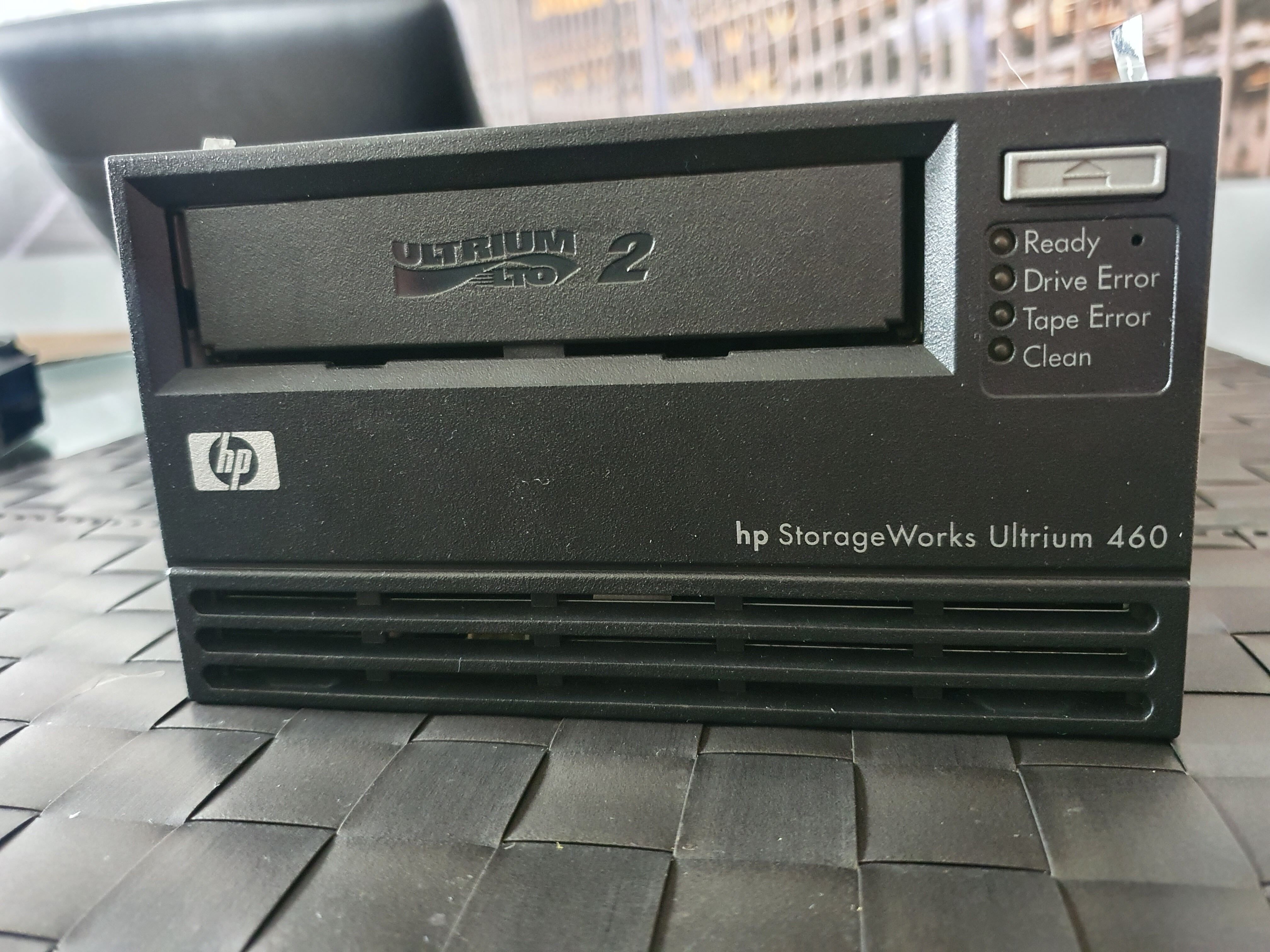
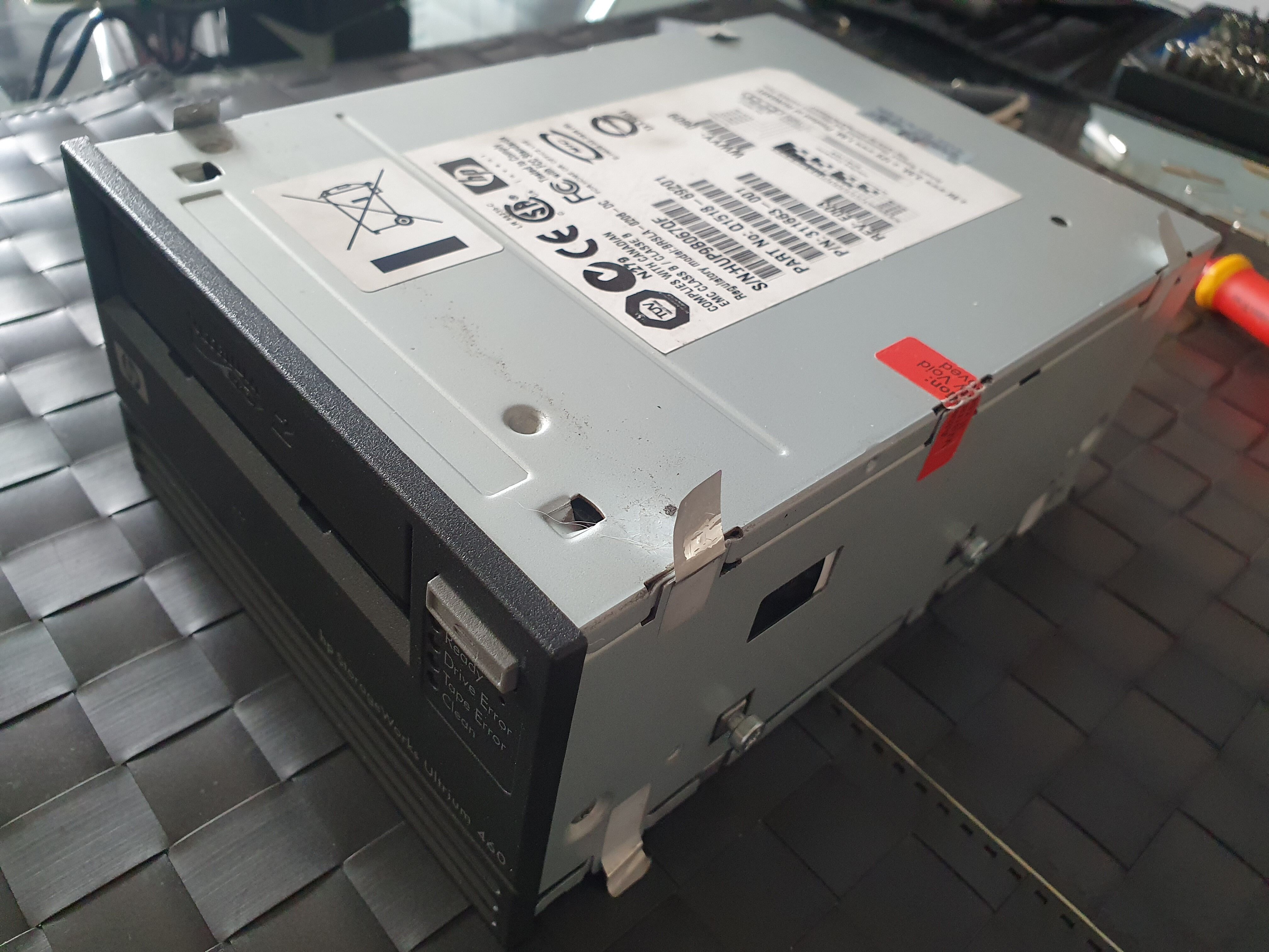
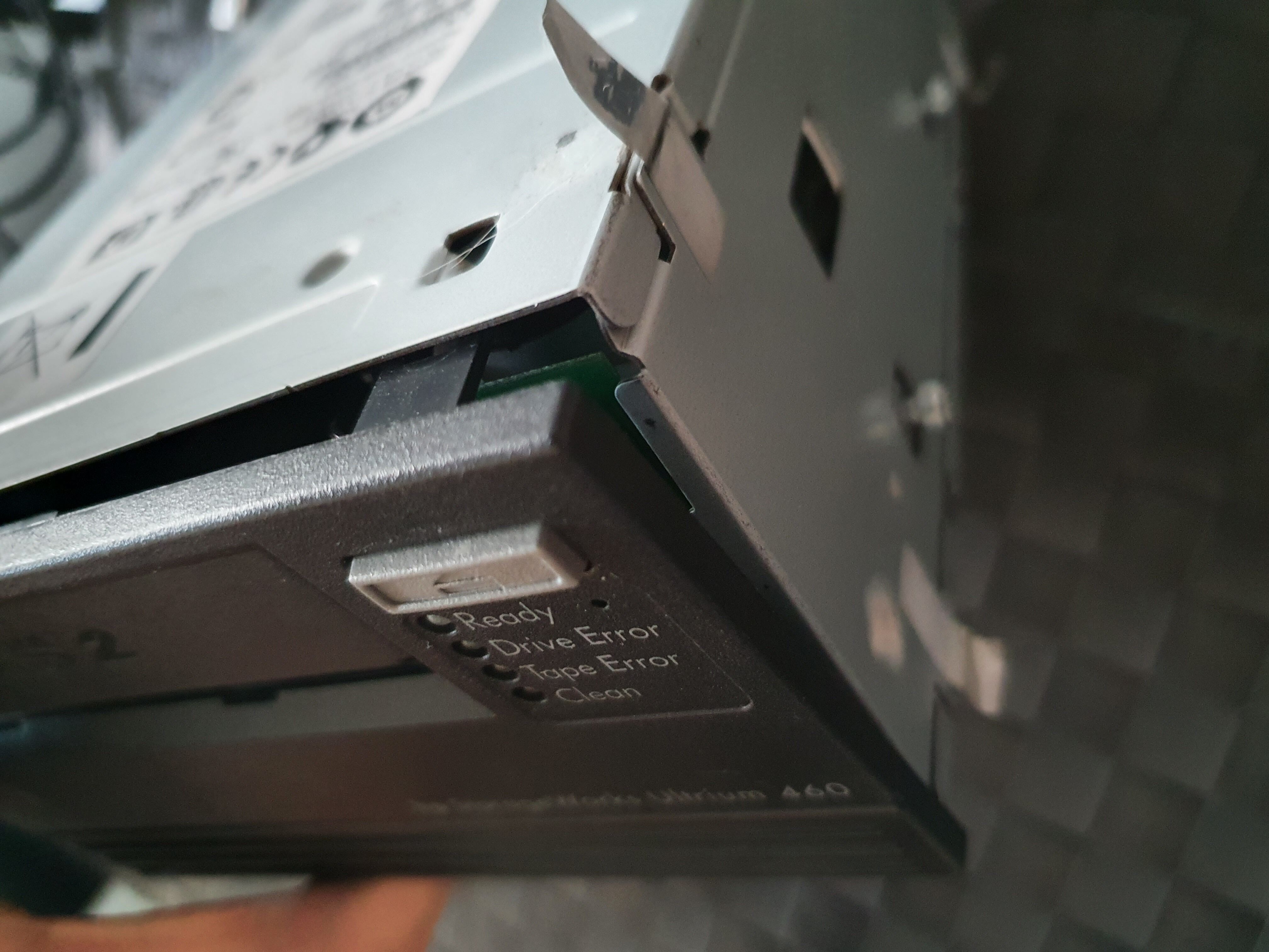
Second drive: external HP StorageWorks Ultrium 460 LTO-2
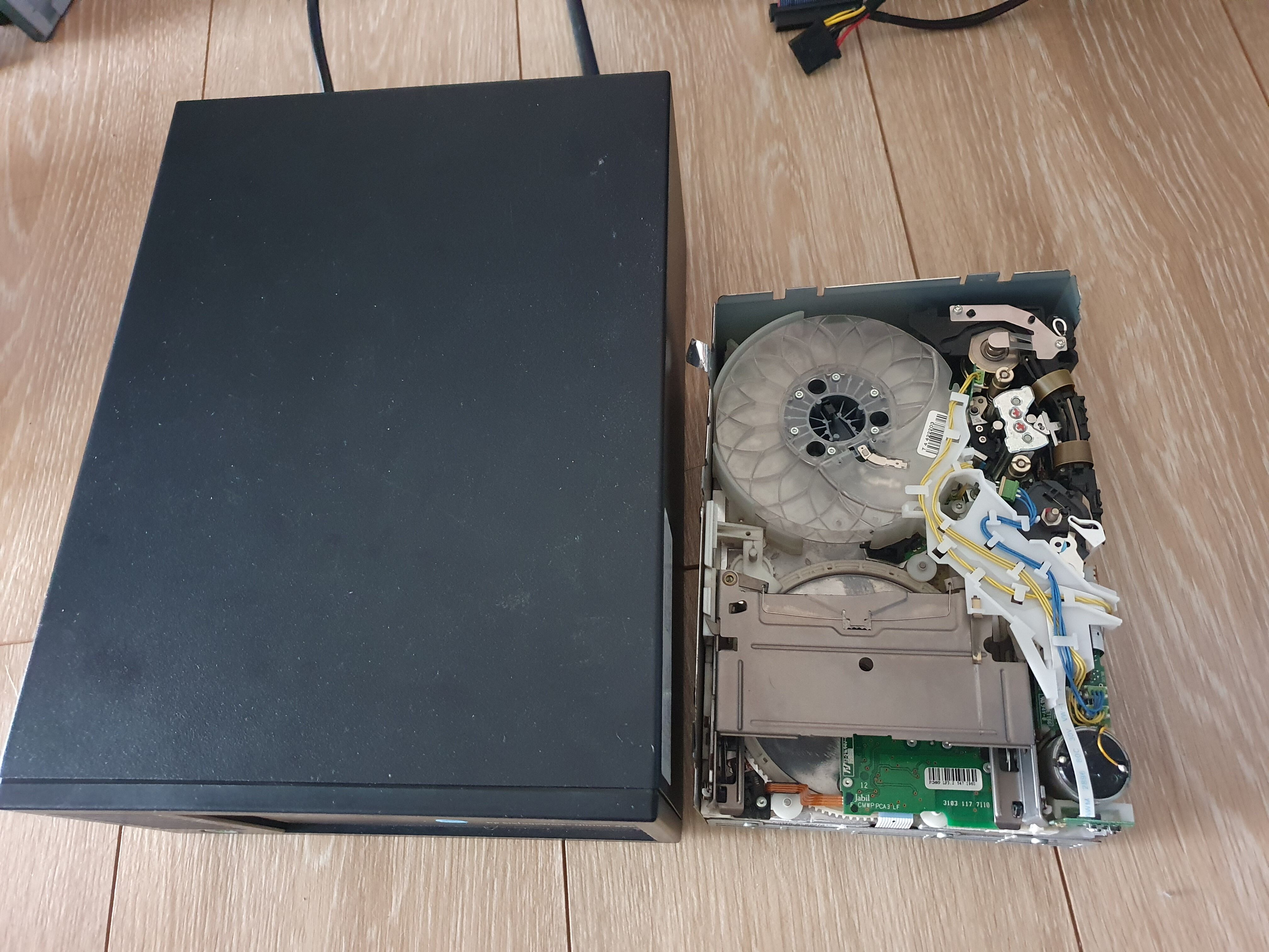
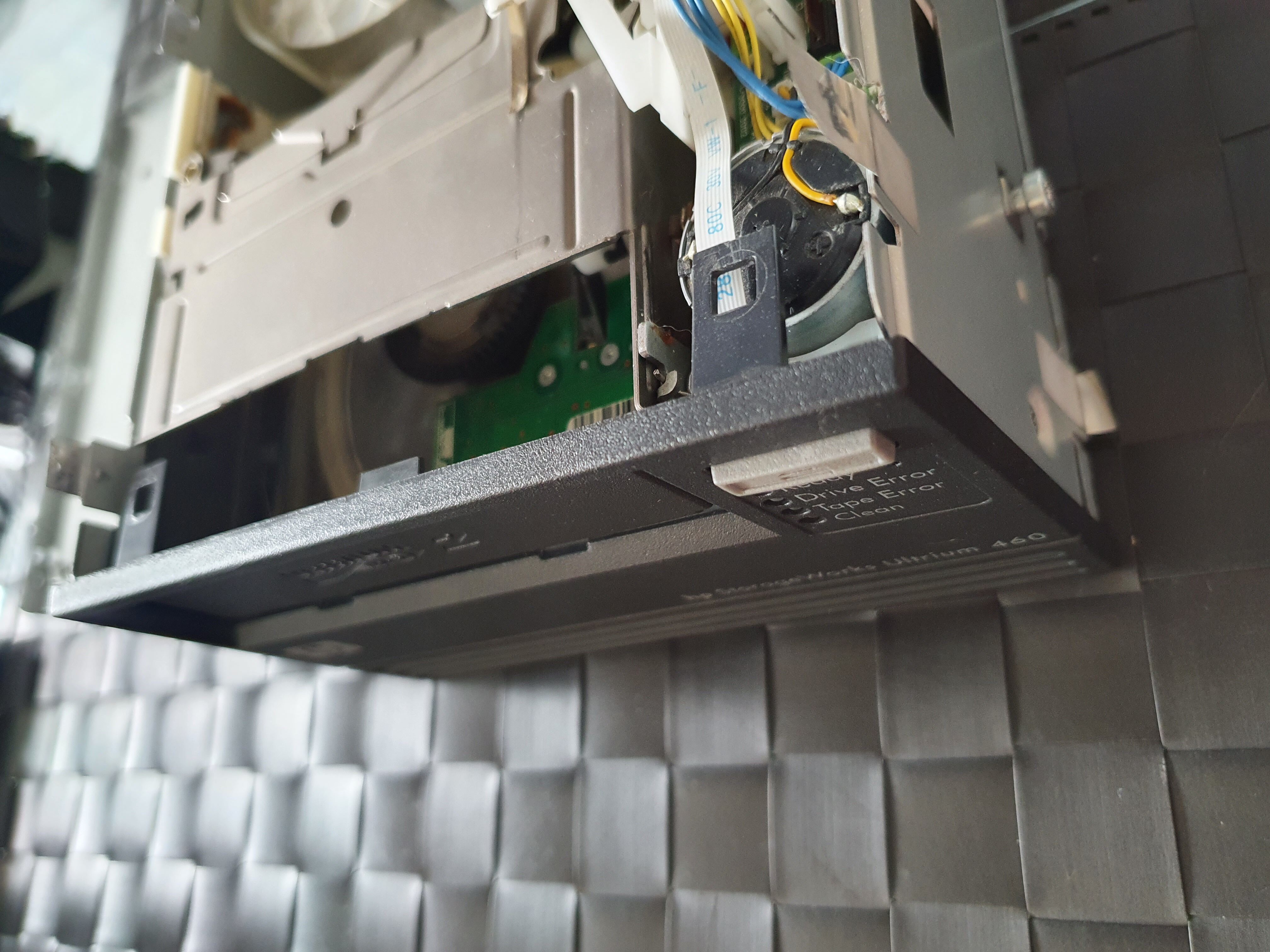
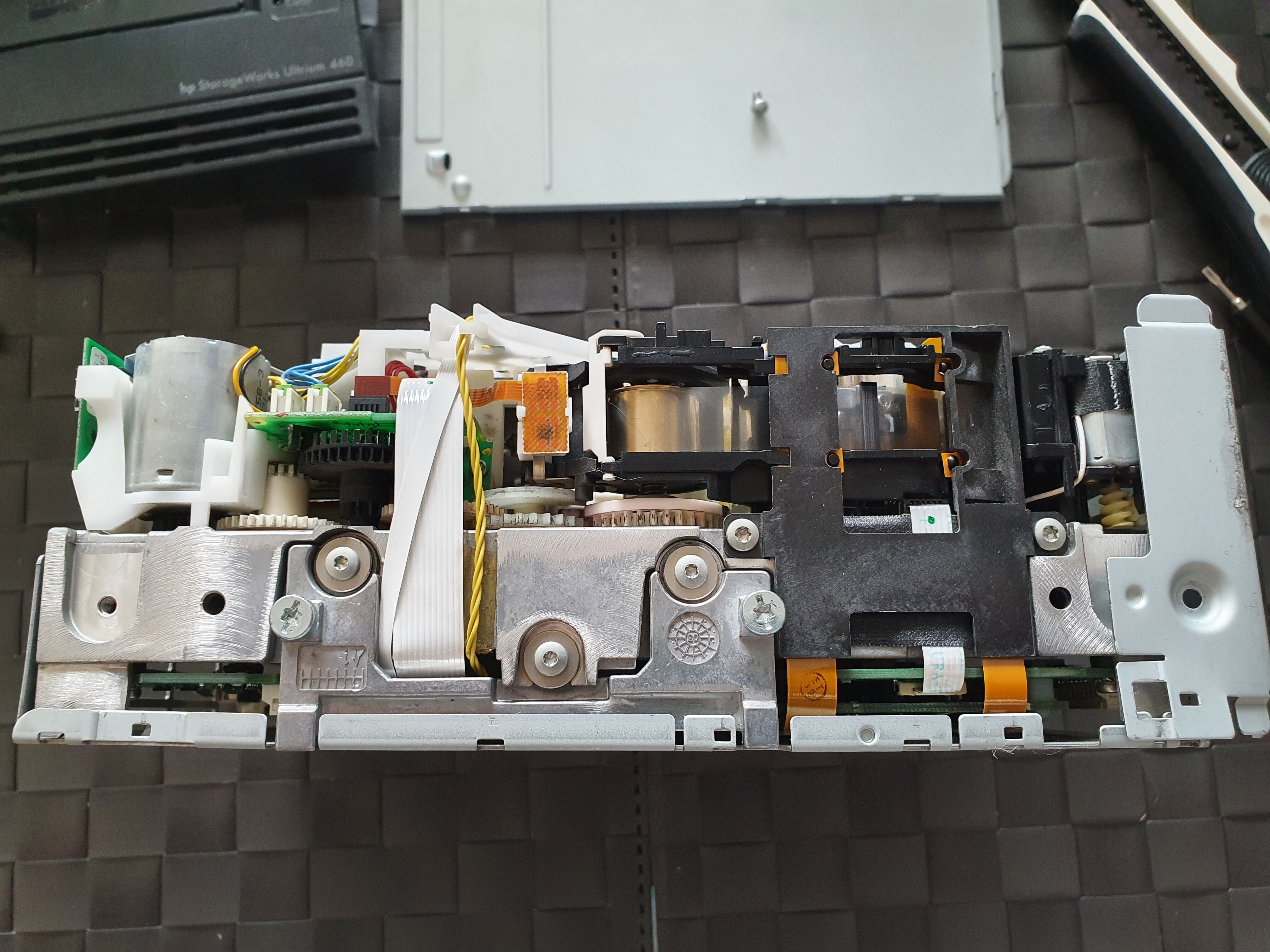
The external drive is more massive than the internal one, which can be seen on the last image above, side by side for comparison (the internal drive has its cover removed).
It was marked as being functional by the seller, extracted from a freshly unracked server, in a proper 24/7 cooled server room. This sounded reassuring, with respect to the other drive which was sold in unknown condition (well, I took my chance, I lost). As the two drives are of the same model, I thought that even if this drive ended up having some minor problem, I could use the other drive’s parts to build a functioning Frankendrive. The first drive I had seemed okay, except for the magnetic heads, so any other part could probably be useful as spare for this second drive.
The report generated by HPE L&TT right after first plugging the drive was way better than the first drive I got:
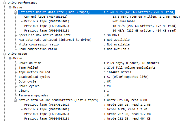
What’s interesting is that this drive has a higher power on time (~6.5 years), but only pulled 1024 Km of tape during that time, and loaded only 57 tapes during its life. This is less that one tape writing session per month!
So, as everything looked well and good so far, I inserted an LTO-2 cartridge, eager to write the first few megabytes on it, but the cartridge got ejected after a dozen of seconds or so. I tried a few other cartridges, of different brands, but no luck: the drive still ejected everything I pointed at it. I attempted a drive assessment test in L&TT, which failed after a few seconds. Needless to say, I was feeling quite disappointed. This is how it sounded like (headphones warning):
Hear the clicking sounds from 0:07 to 0:19? We’ll come back to these in a few moments.
After I tried a few cartridges, a few assessment tests, and a few power-off / power-on cycles, I was running out of ideas. The reports from HP L&TT were turning red:

A lot of bad news here.
1
2
The drive has experienced a fatal head calibration error.
Please contact support for further information.
Typical of professional-grade equipment, when something off is detected, the tool just tells you to contact the vendor support, and calls it a day. Head calibration error sounds particularly bad, especially because the first drive I bought also had worn out magnetic heads, so if that second drive had problems with its heads too, then I couldn’t use the other drive heads to fix this one.
1
2
Problems were found with the format of the data read from the tape cartridge memory.
Please try using a different tape (ideally one that has been confirmed to be good in another drive, otherwise try a new tape).
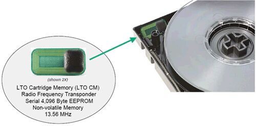
This one indicates yet a whole new range of problems. LTO cartridges contain a little RFID memory chip, where cartridge usage information is stored, along with its serial number, format, and a few other metadata things. This memory chip is known as the Cartridge Memory (CM), which is the name given to the Media Auxiliary Memory (MAM) of LTO cartridges. If the CM can’t be read, the data from the cartridge can usually be salvaged by flipping the write-protect switch of the cartridge to ON. In this case tape drives will usually ignore the fact that it can’t read the CM and accept reading the data from the tape. This is reassuring, otherwise this CM would be quite a SPOF!
A lot of different errors were also logged:
1
2
3
4
0x1c00 DR_ERROR_BAD_CART_TYPE (Attempting to Load a cartridge of a type that Drive Control cannot handle)
0x7708 miDspFault_0x08 (DSP Fault- StrokeSizeFlt - The stroke measured by the VI sensor hardware was not large enough.)
0x7712 miDspFault_0x12 (DSP Fault- CalibIDFlt - Unable to verify band ID on a top servo band.)
0x750c miWriteFaultDSPDemodChanOut
This confirms the two issues we seem to have: problems with the head, and problems with the RFID chip header. The media assessment test and drive assessment test of L&TT were failing almost instantly, as the drive was rejecting all cartridges anyway. An interesting data point was that cleaning cartridges were behaving differently: the drive wasn’t ejecting those immediately, but just sat there without doing anything once the cartridge was inserted. The only way to eject it was to power cycle the drive.
At that point I decided to take the drive apart, hoping I would be able to do something. Get your Torx ready!
Disassembly
This disassembly guide is valid for internal and external HP Ultrium drives. If you have an internal drive, you can directly skip to the next section.
External drive
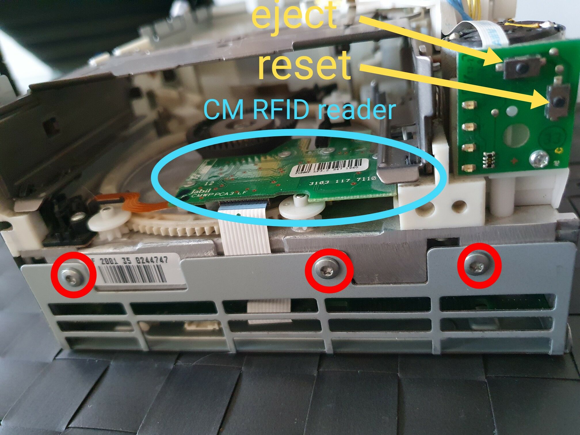
First, you need to remove 5 screws:
When this is done, you just have to slide the cover, and will end up with this:

The enclosure contains a builtin power supply, a board with an embedded SCSI terminator, and the drive itself, which is the same than the internal one.
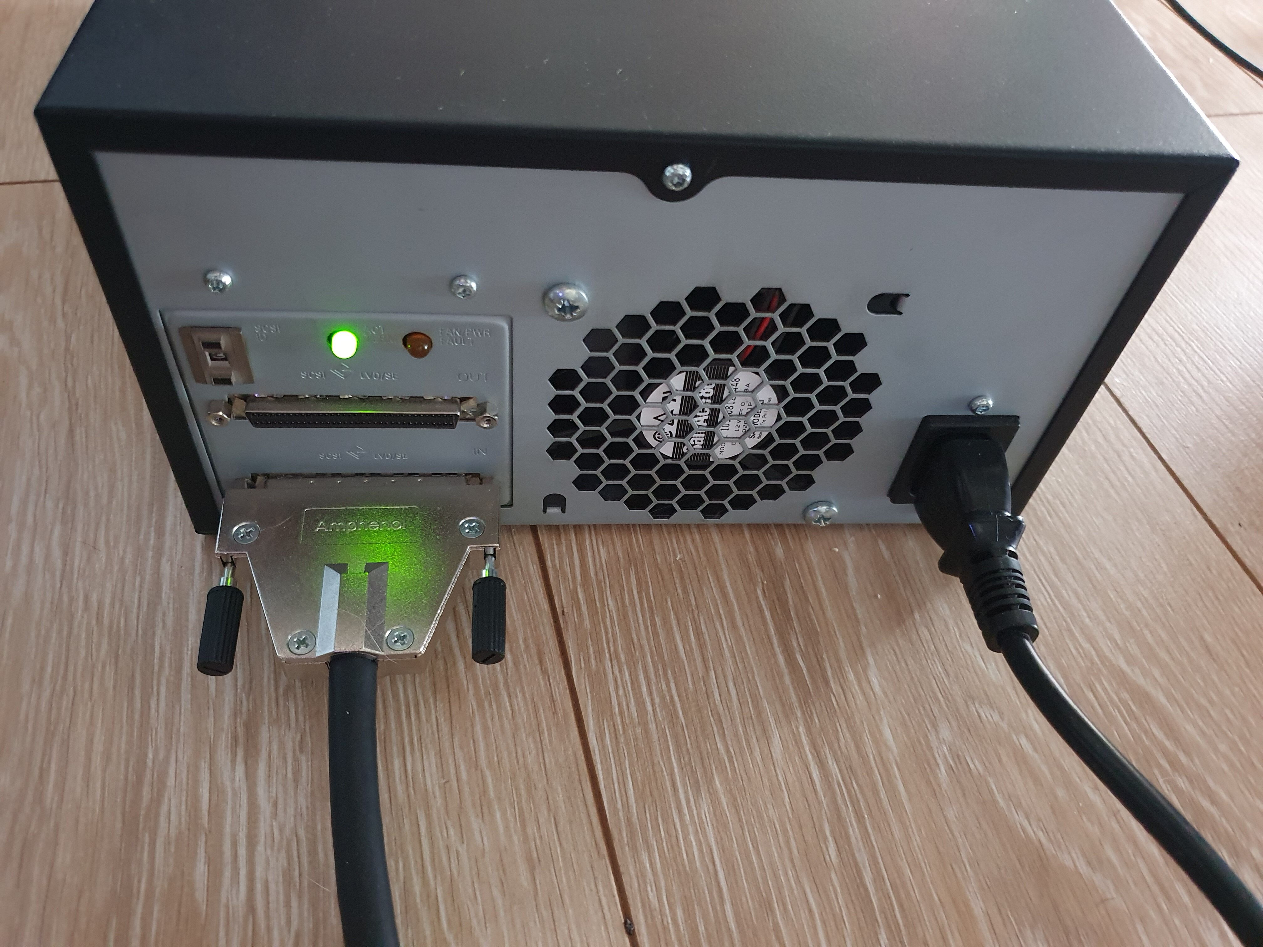
A better view of the board and the (very loud) fan:

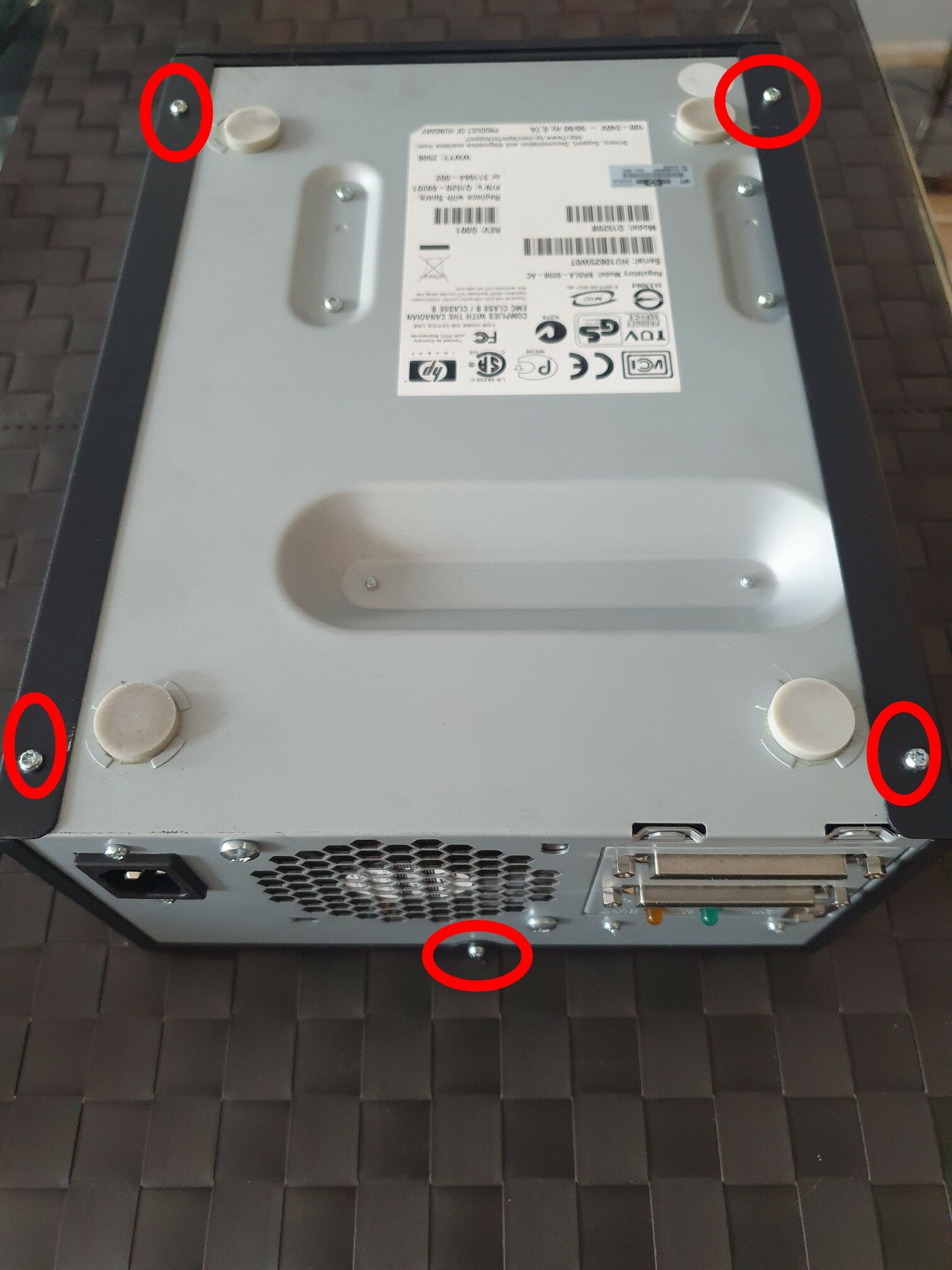
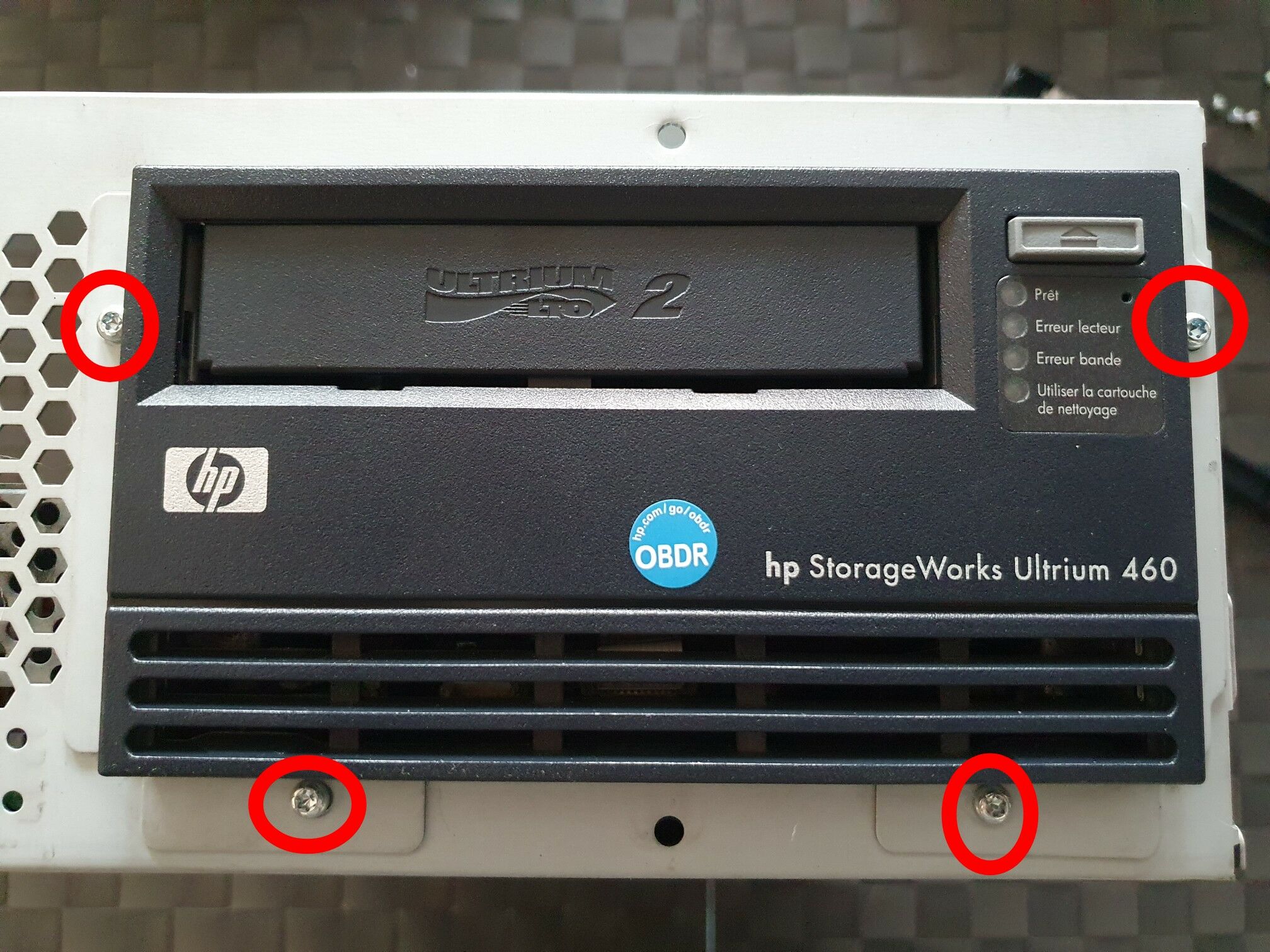
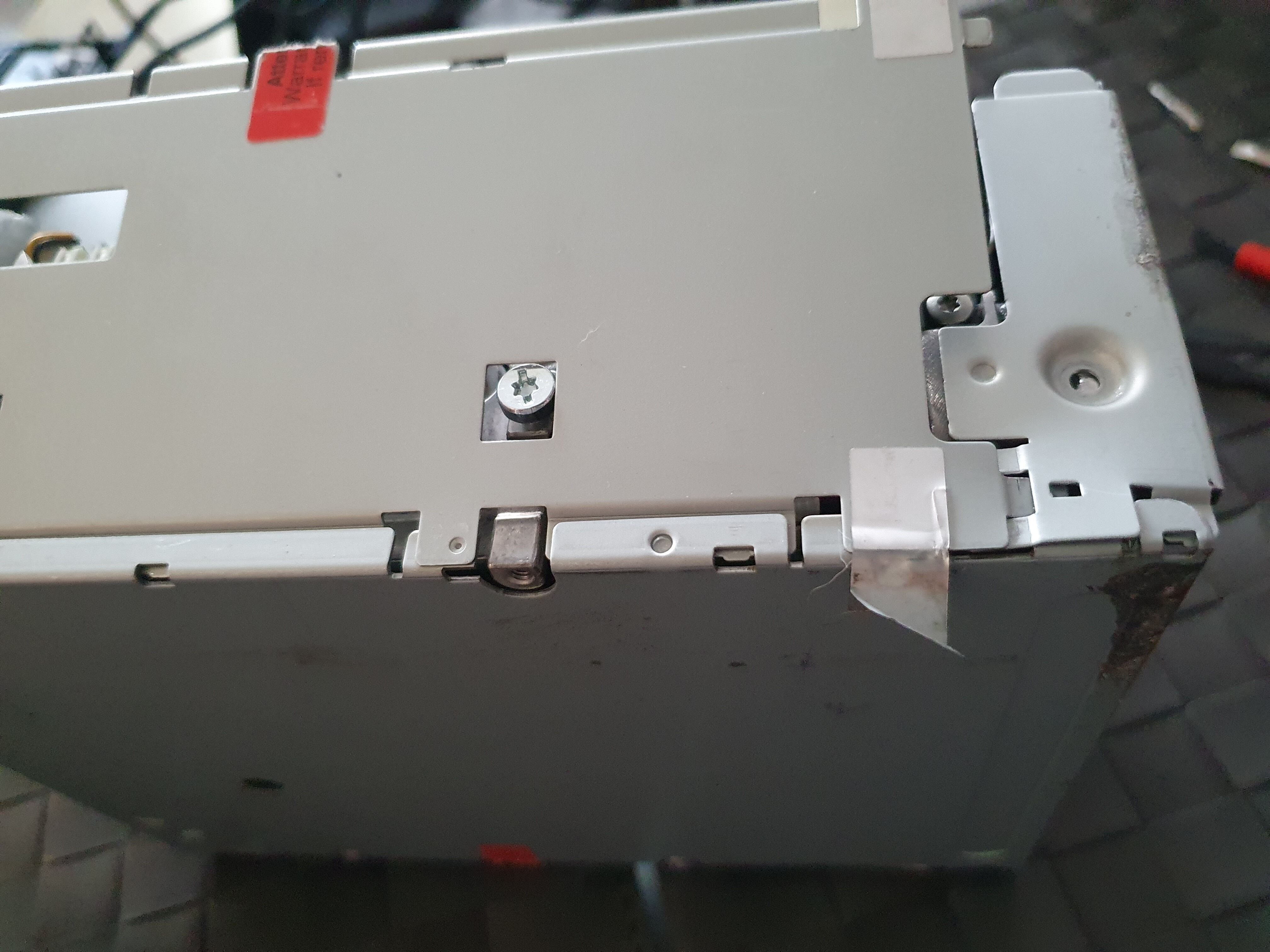
To be able to remove the internal drive from the enclosure, you need to remove 6 more screws. 4 screws on the front:
And 2 screws on the back of the internal drive, locking it to the enclosure:

When the 6 screws are removed, you can slide the internal drive out of the enclosure. There will be two metal plates left, one on each side of the drive, easily removable along with 4 more screws (forgot to take a photo of this, but it’s very straighforward).
You should end up with the bare internal drive, and can proceed to the next section.
Internal drive
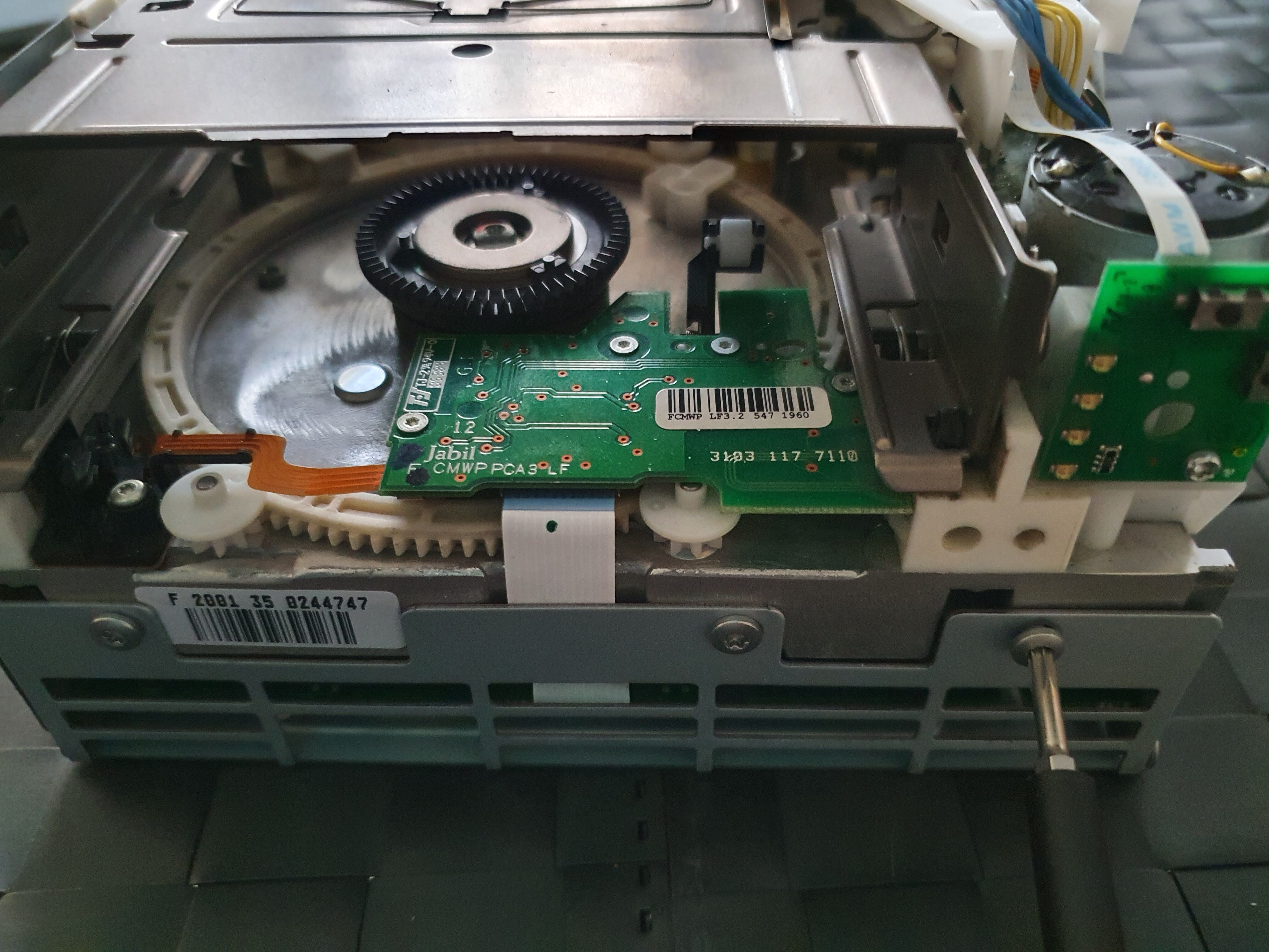
Here is how the internal drive looks like:

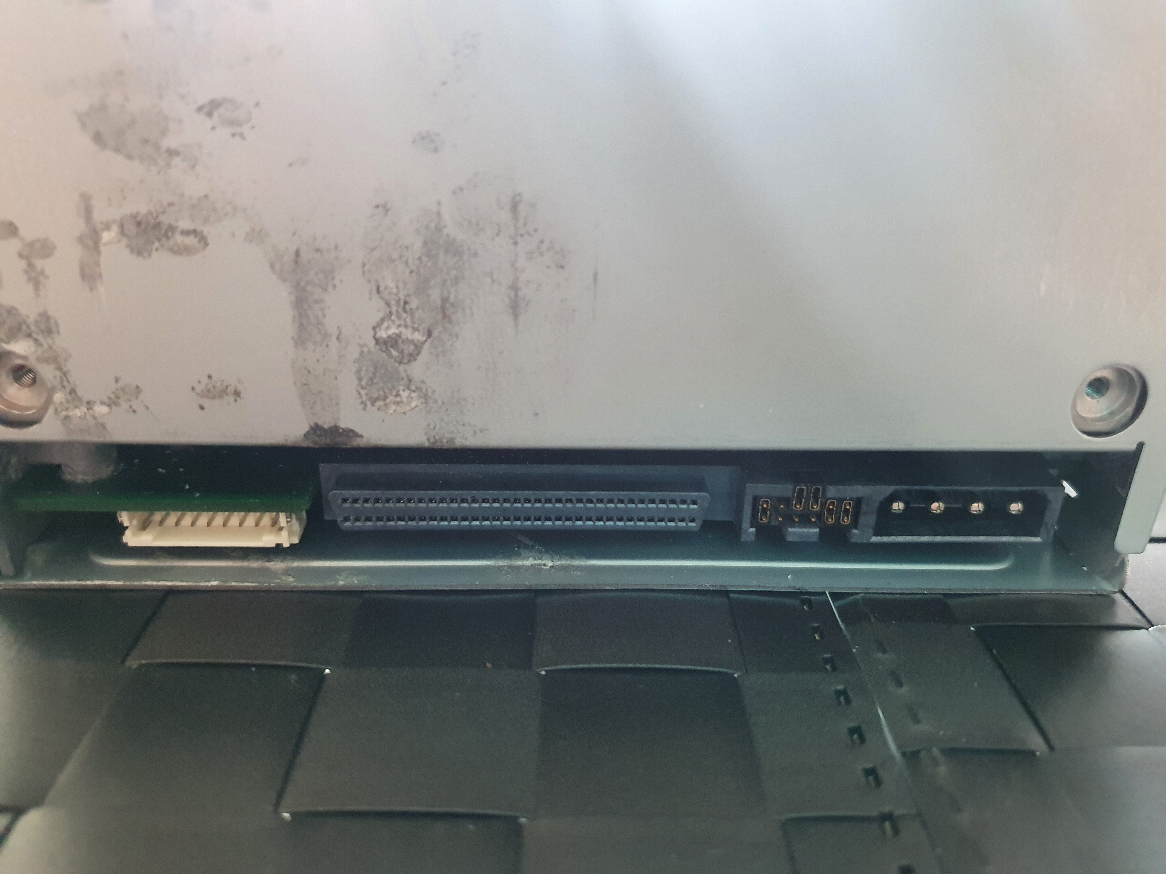
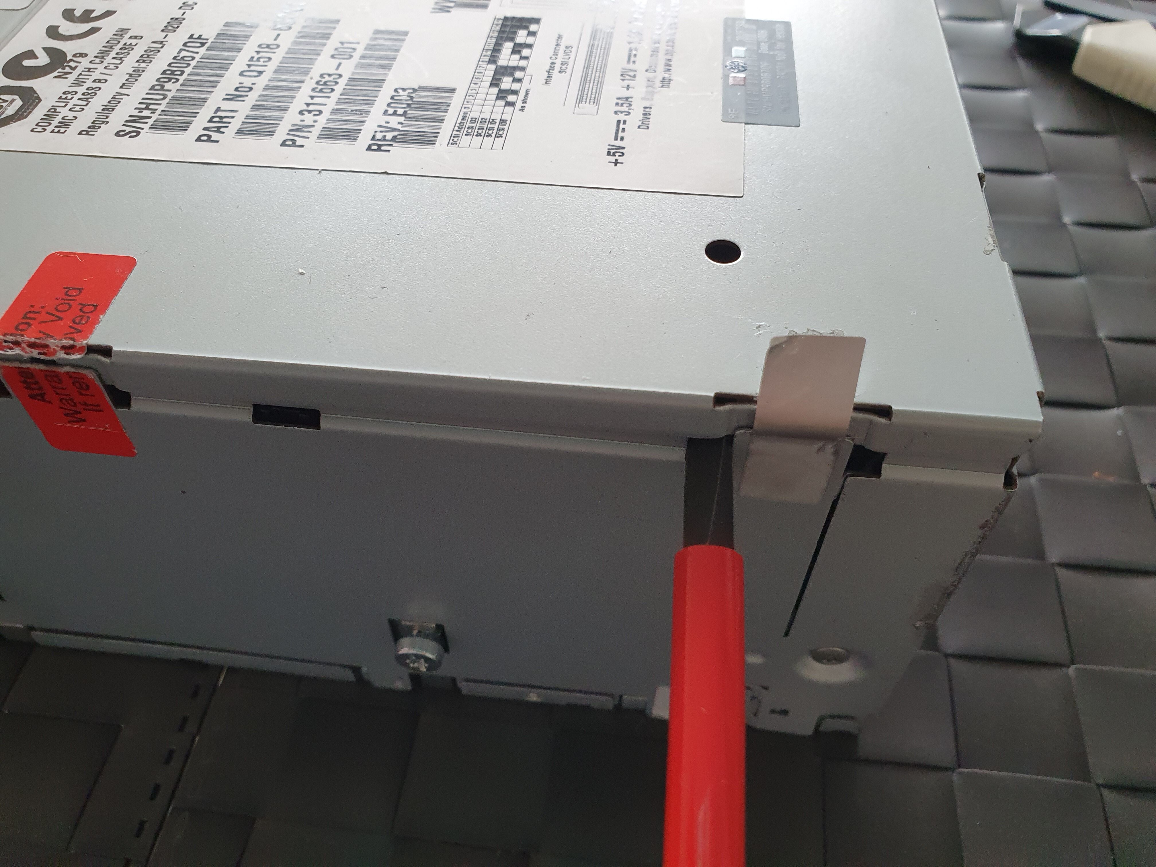
Now let’s open it! Ready to void warranties?
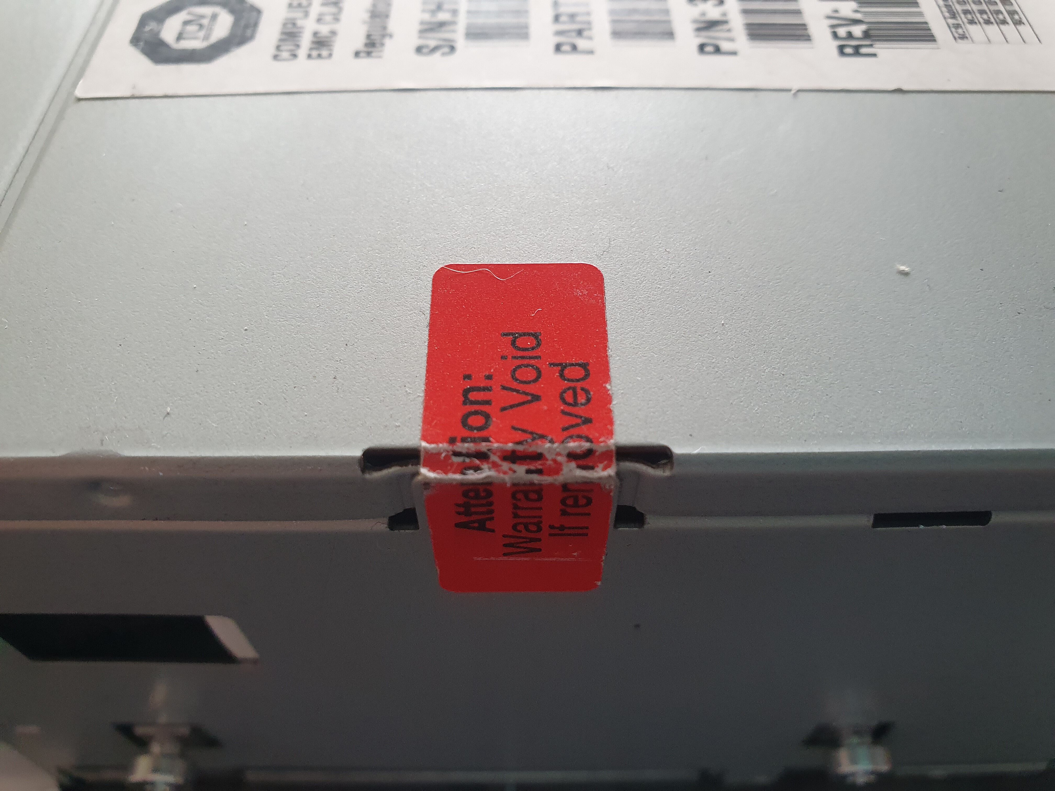
First, we need to remove the top cover. Interestingly, there are no screws here, just grey stickers, and a “void warranty” one. You need to get the stickers out of the way (by lifting them for example, as can be seen on the photo below), and use a screwdriver to gently lift the cover on the 4 sides as shown:
As we’re at it, let’s remove the front bezel, there are just 4 plastic clips, and only 2 remain, as we already removed the top coverr:
We can finally see the inside of the drive. We need to remove the right cover, 2 screws need to be removed:

The right cover should be easy to remove, you just need to slide it gently, as it’s inserted in the bottom cover and the left-back cover:
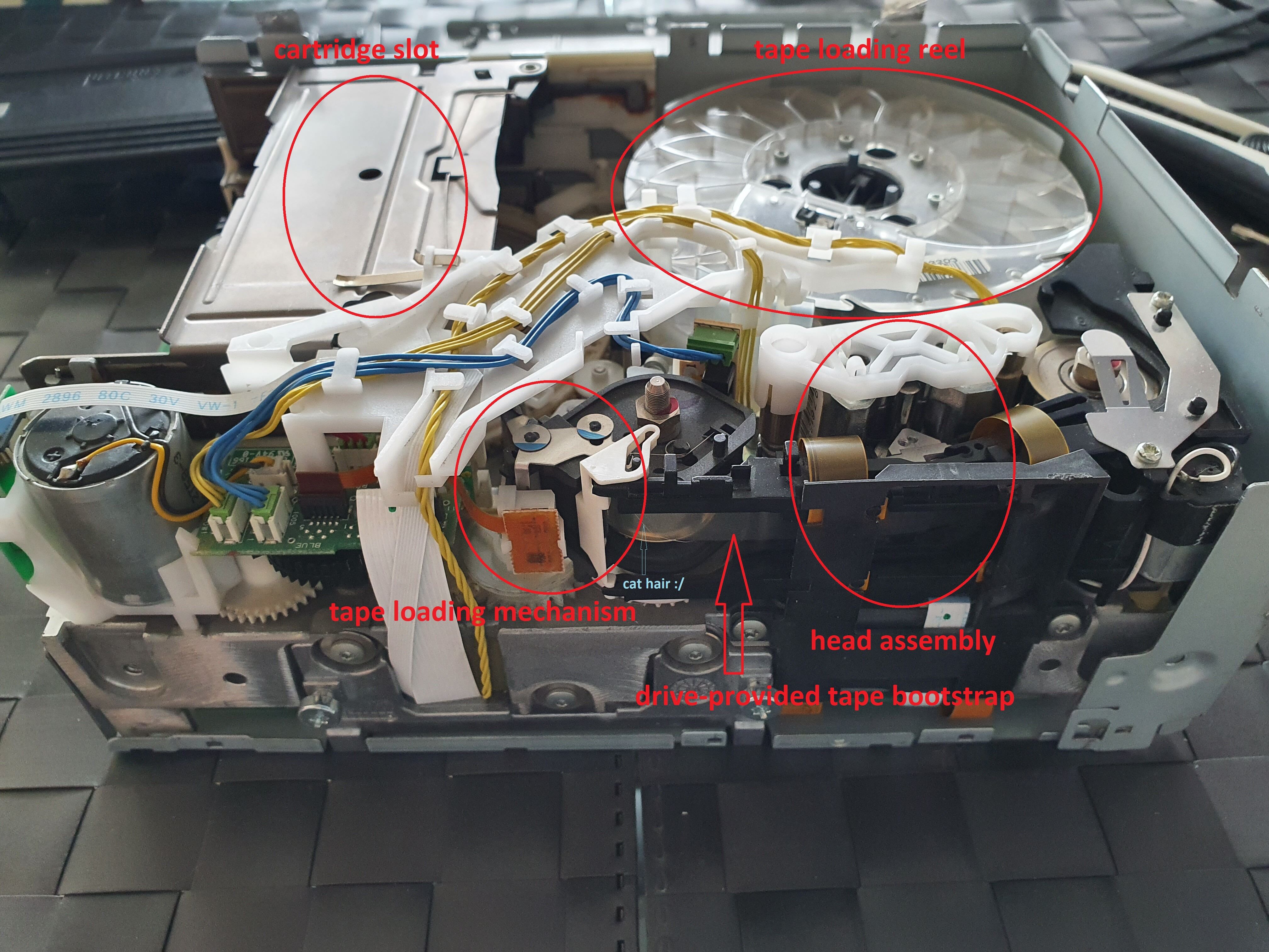
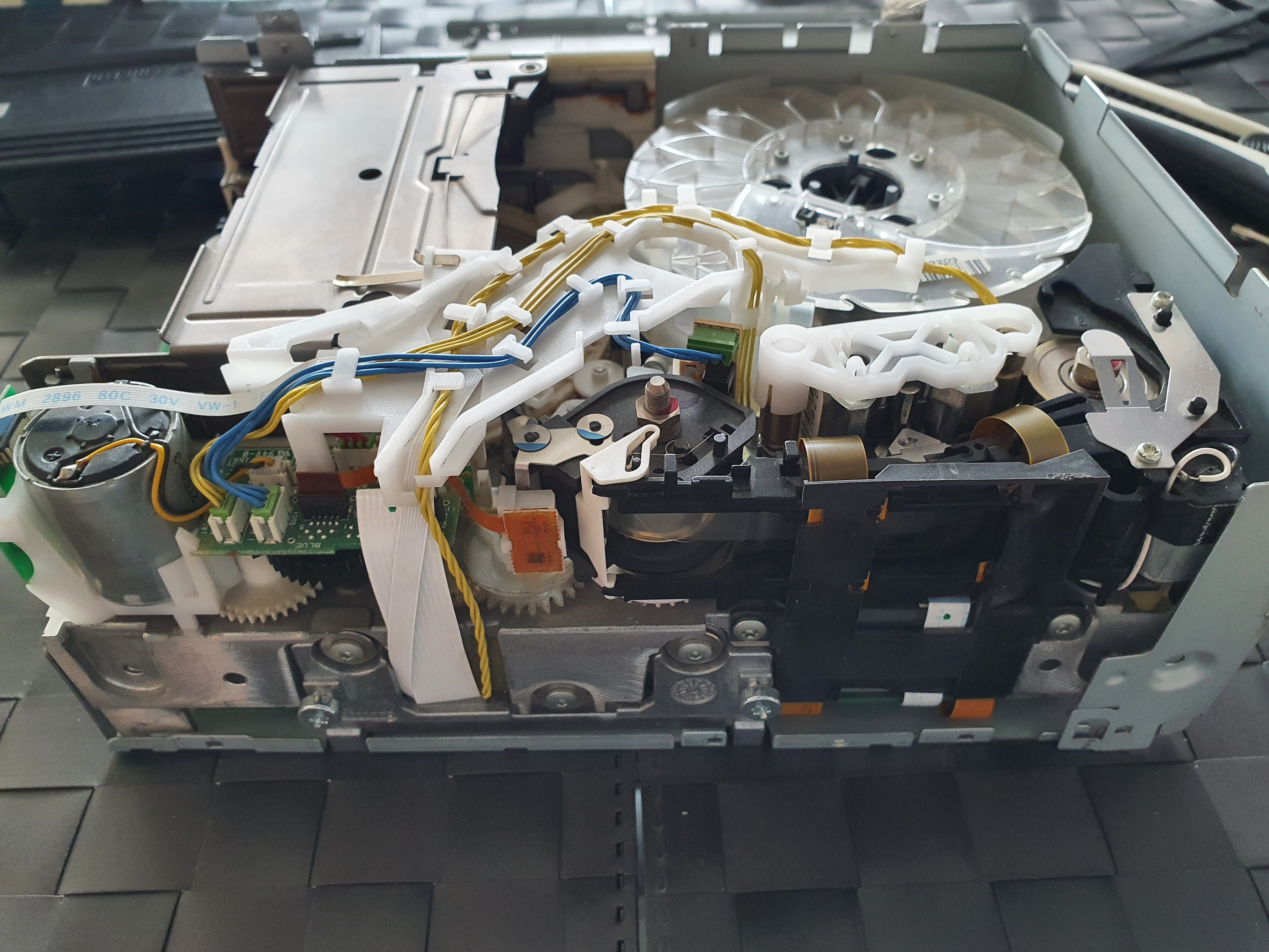
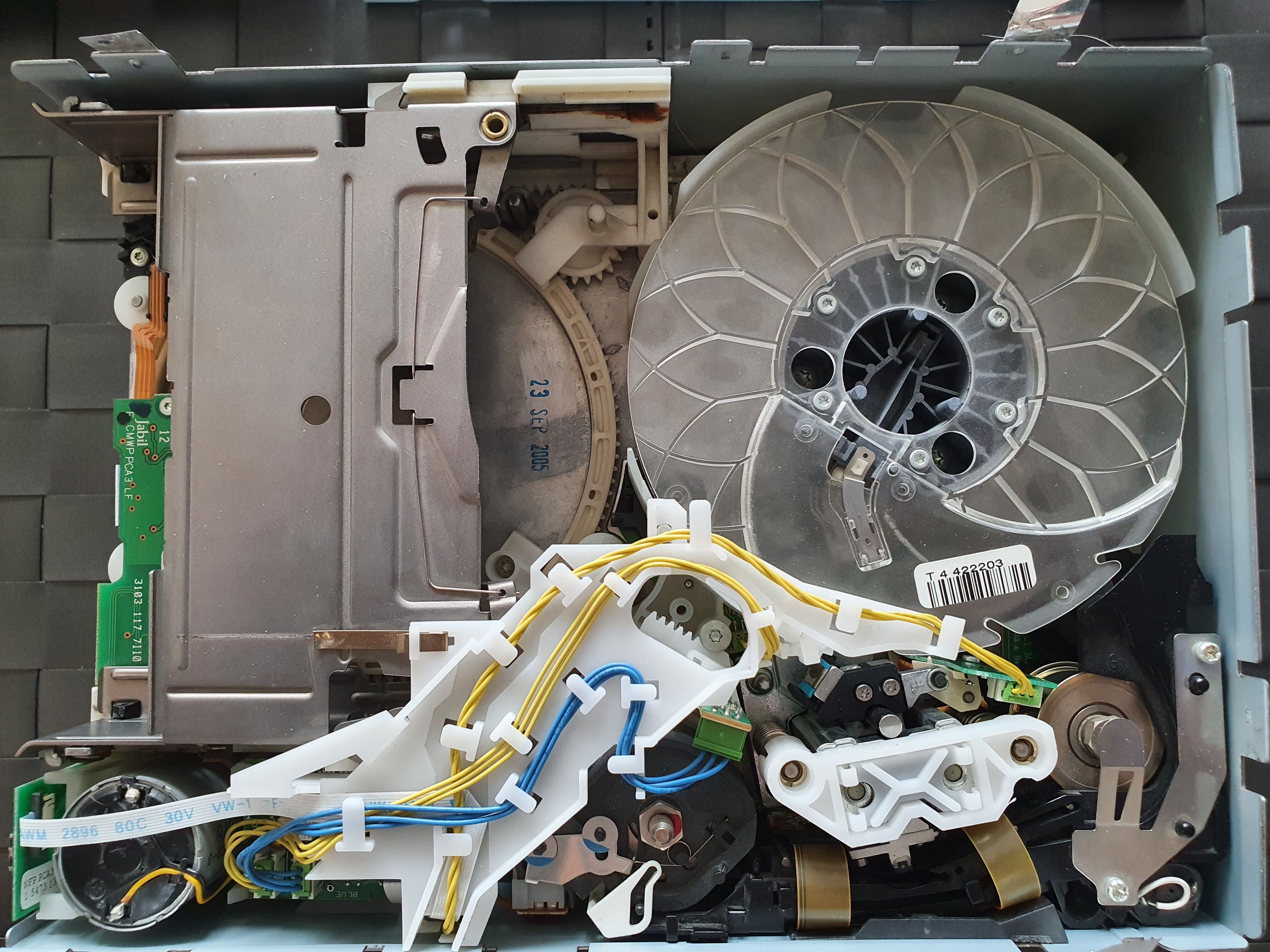
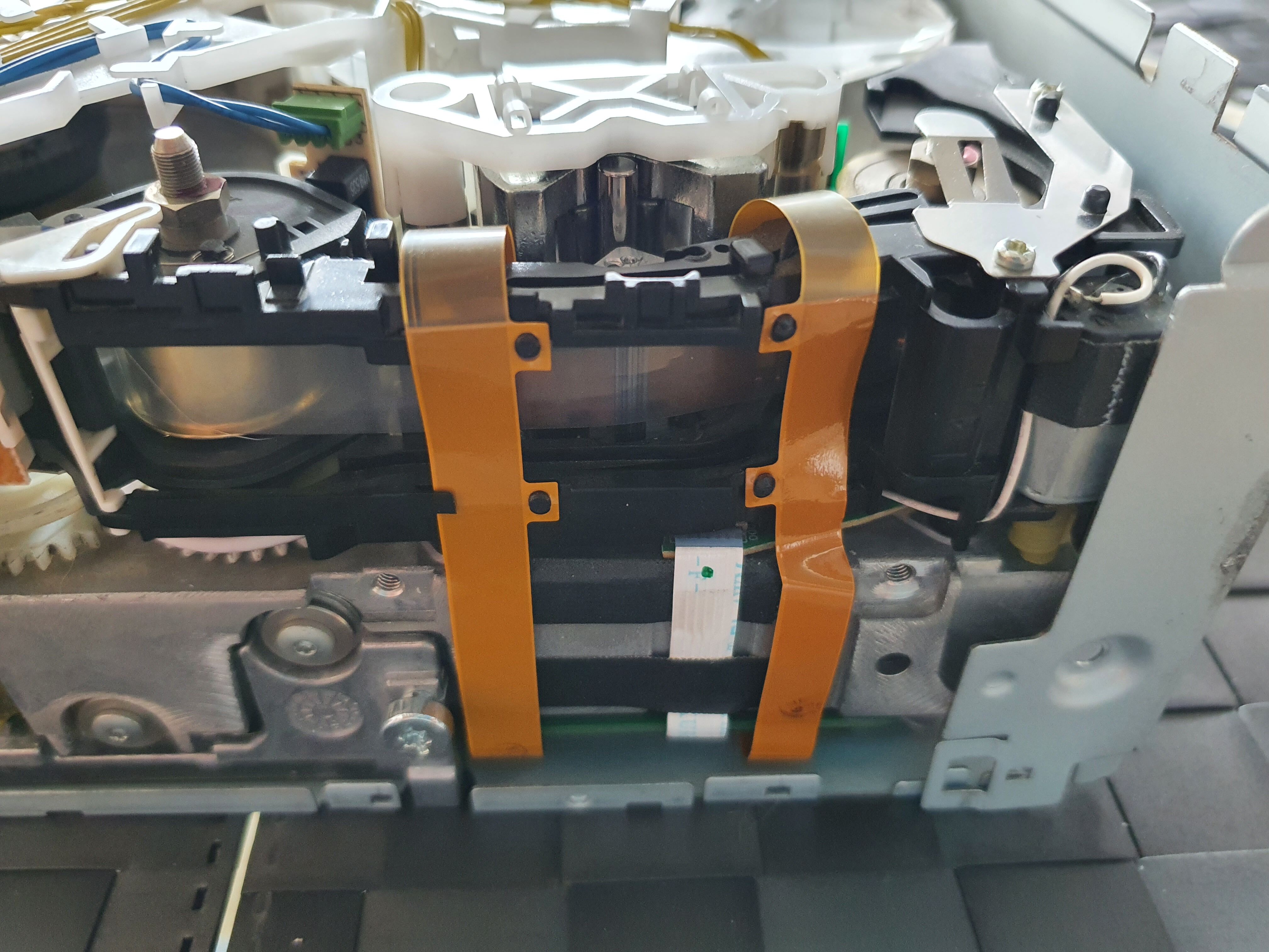
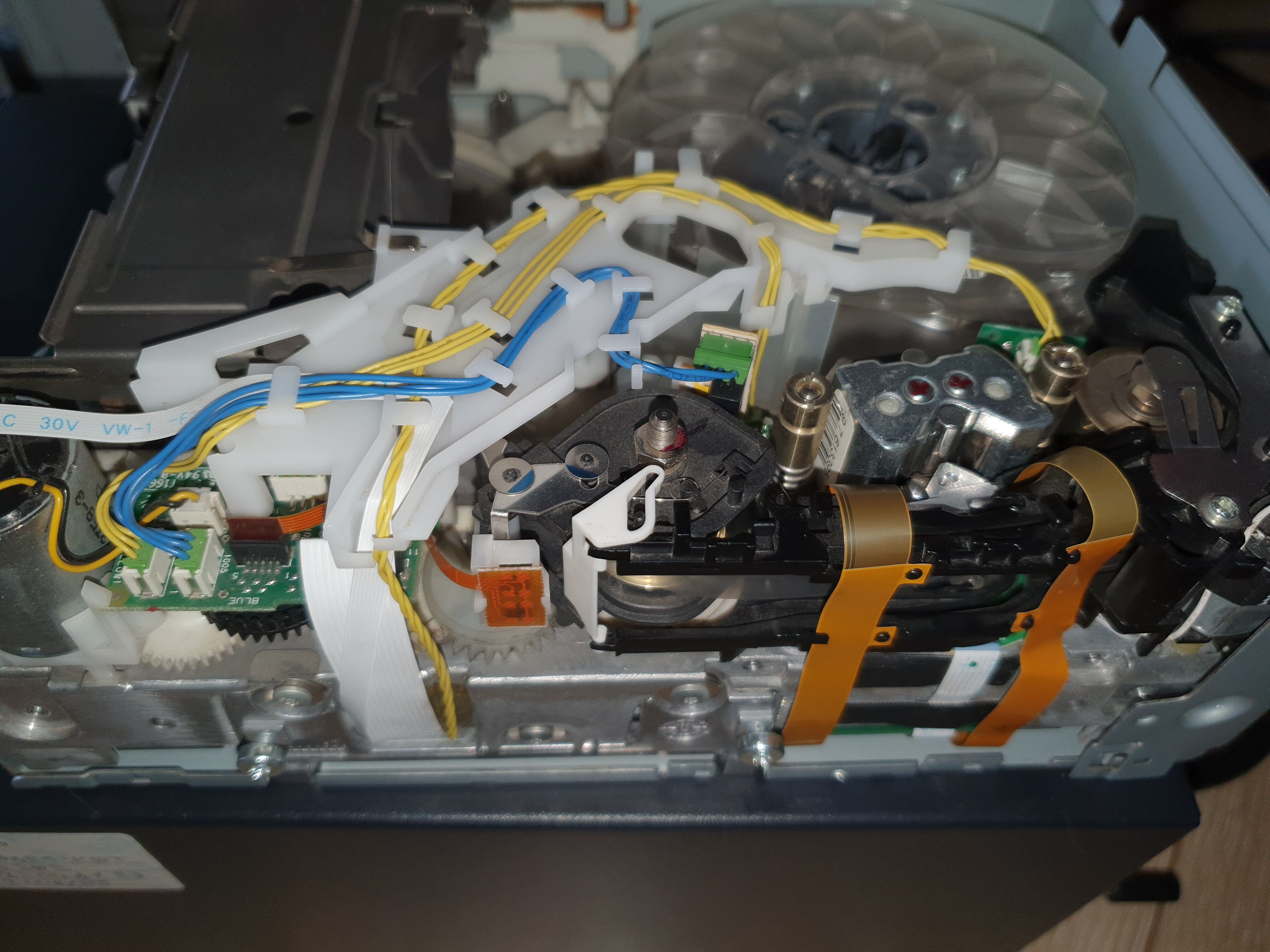
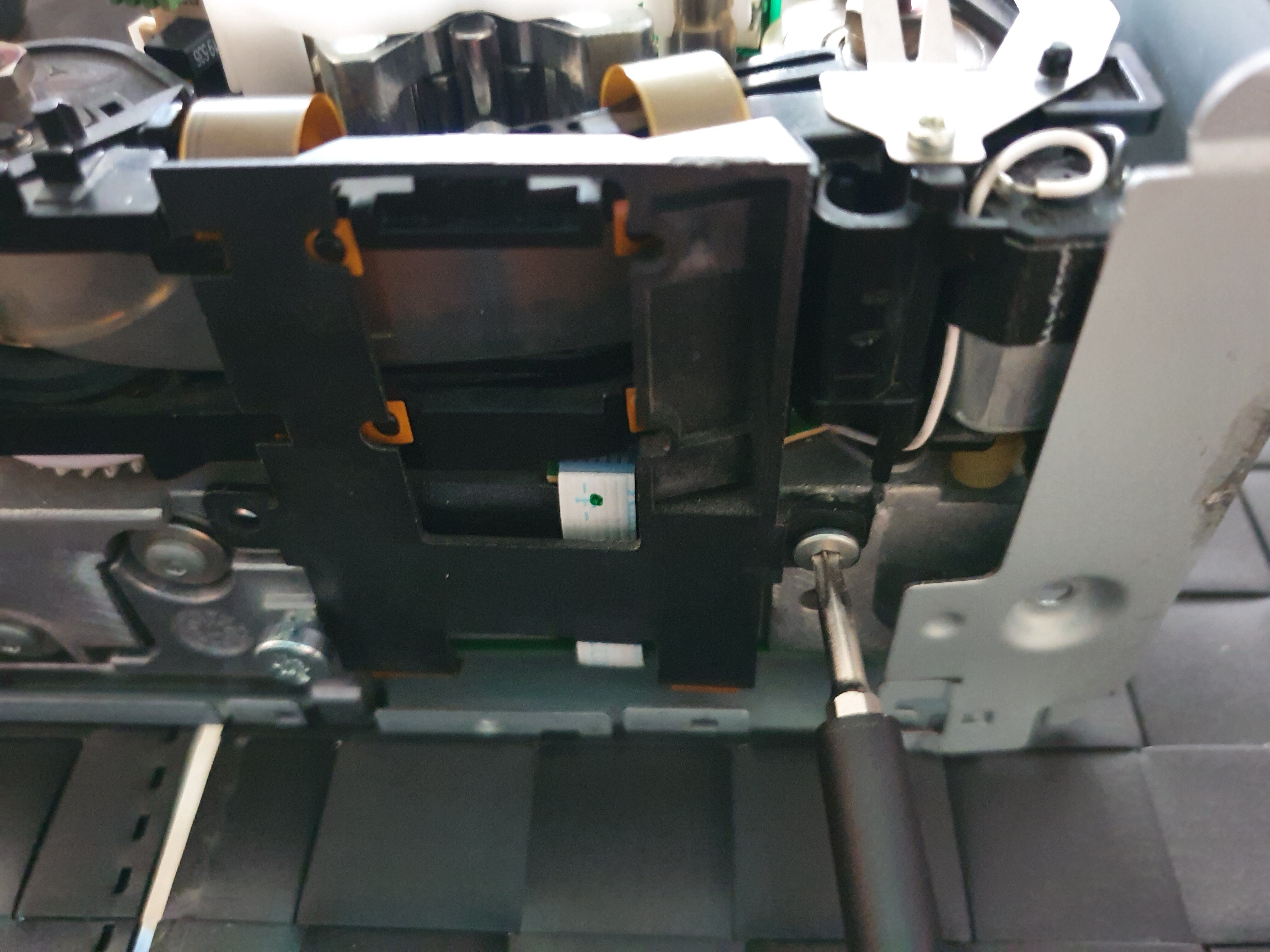
Now we have a better view of the drive mechanics:
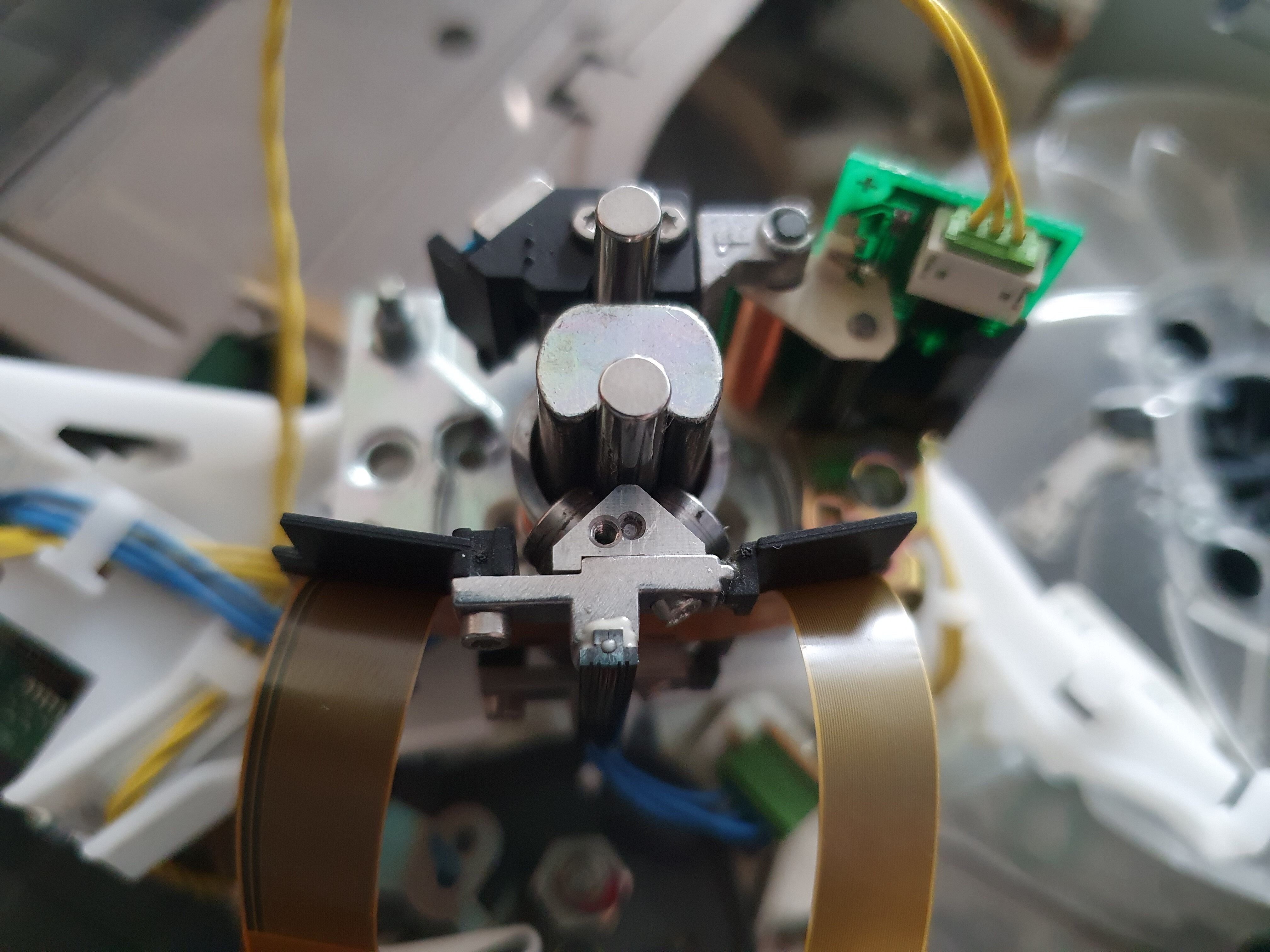
Let’s zoom in on the head assembly. There lies the problem of our drive. The head assembly should slide on the vertical axis very easily, with no friction: as this is driven by magnets, any friction is a problem. If you want to test this on your drive, grab the metal part on the back of the head assembly, as shown, slide it up on the vertical axis gently, then let it go. It should fall with no resistance at all, all the way to the bottom of the vertical axis:
If you can tell that something is slowing it down, then you have too much friction. If it falls fast but needs to be pushed a bit to reach the botton of the vertical axis, then it’s no good either. In my case, there was friction because the head was not really falling freely, it was sliding but something was slowing down its fall. This can happen if there’s a buildup of dust there, or if one of the ball bearings has too much resistance. We’ll need to take the head assembly appart to find out.
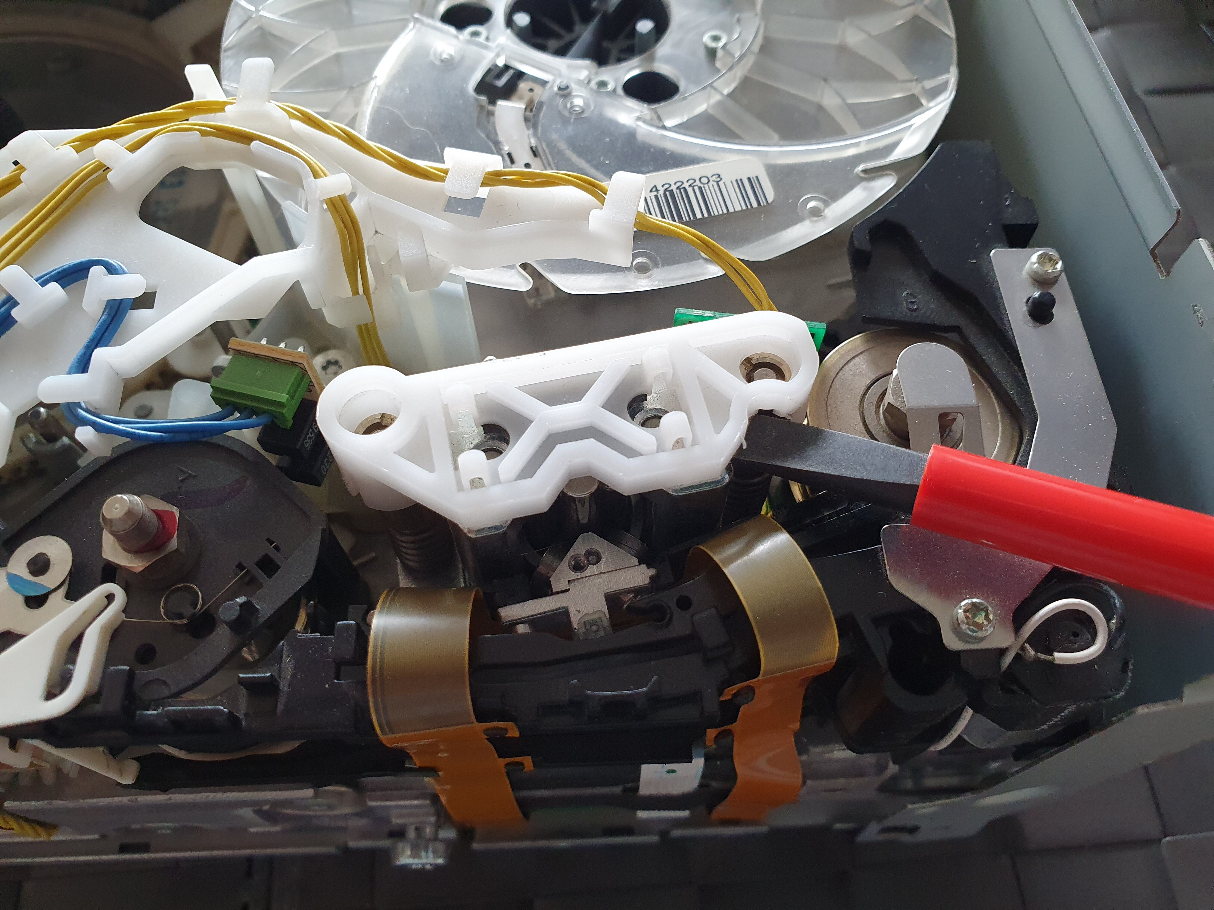
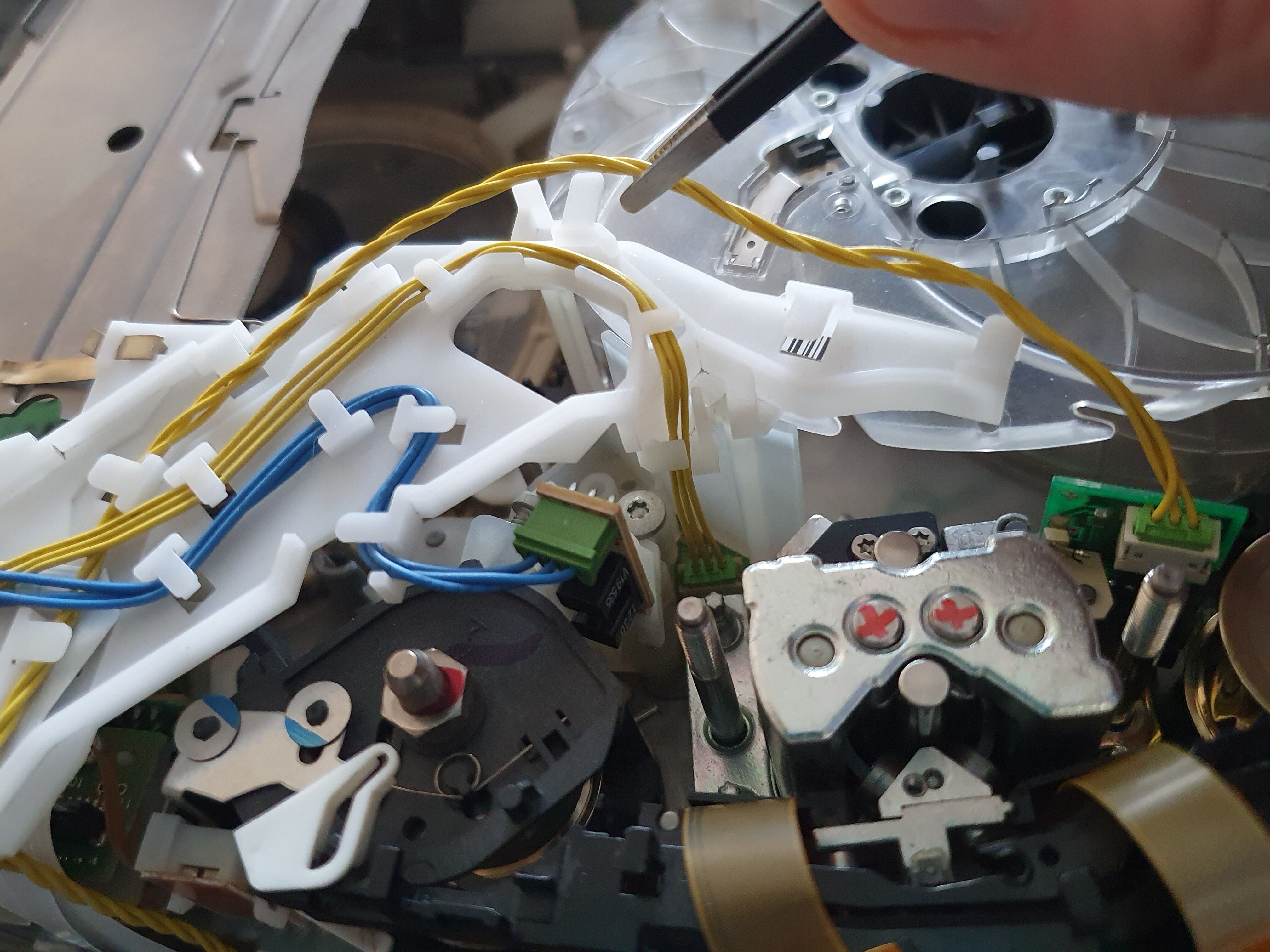
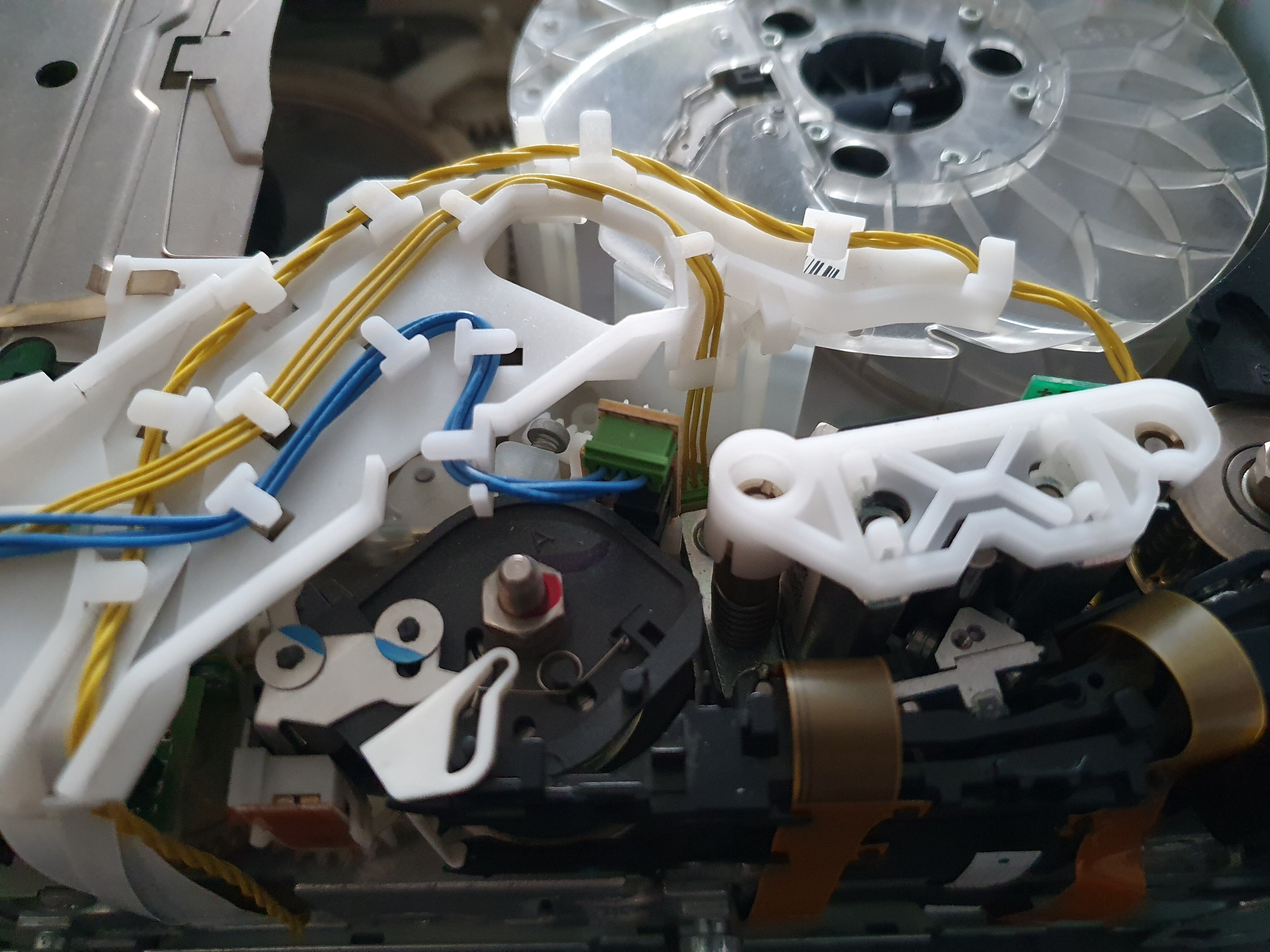
Before proceeding, here are a few photos of the drive mechanics:
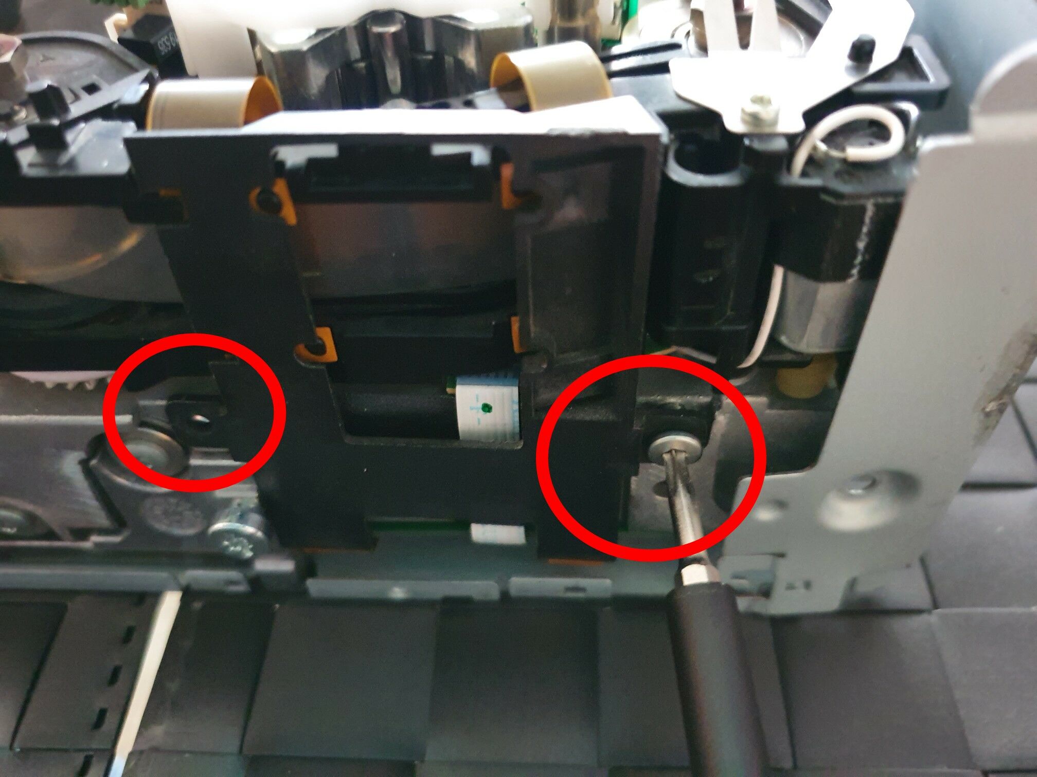
So, let’s remove these two screws, the plastic is then easy to remove:
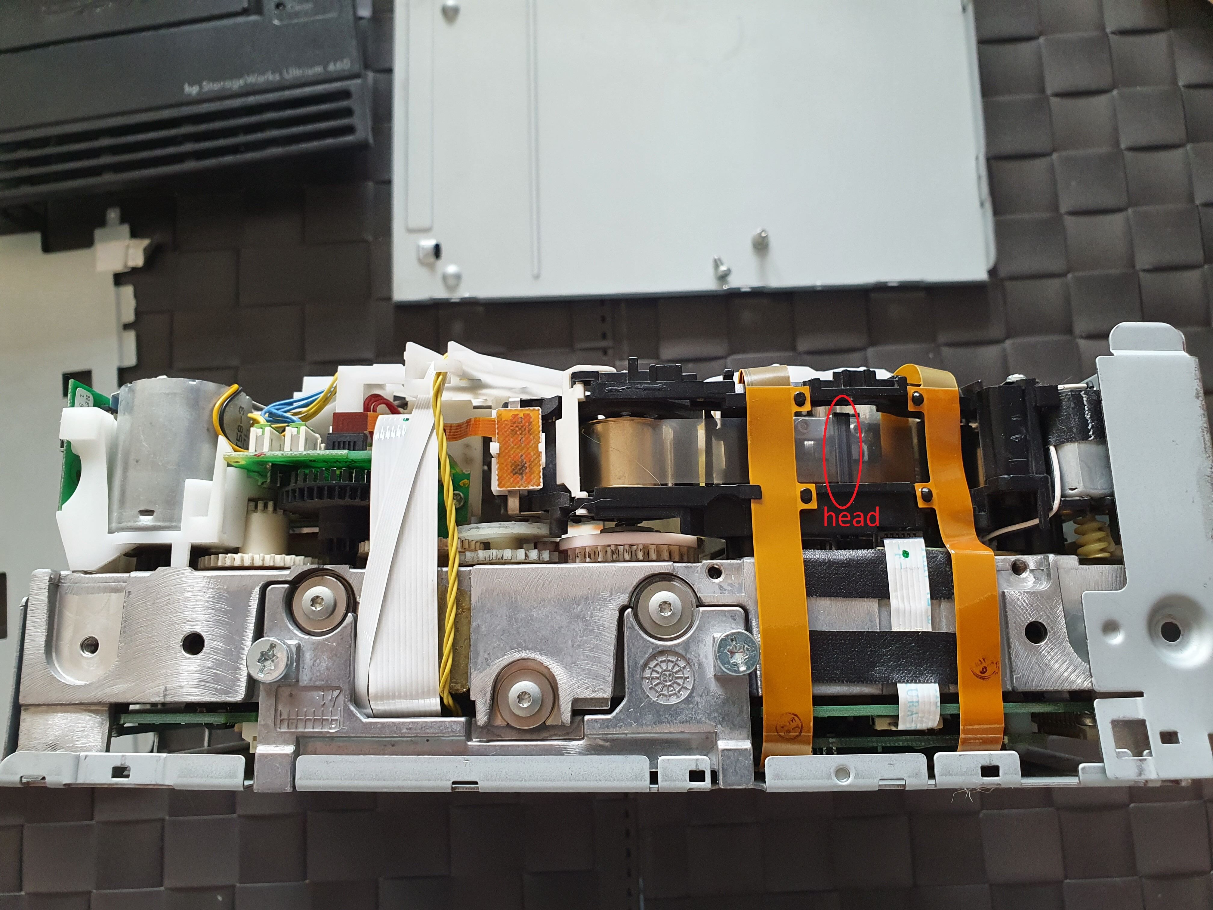
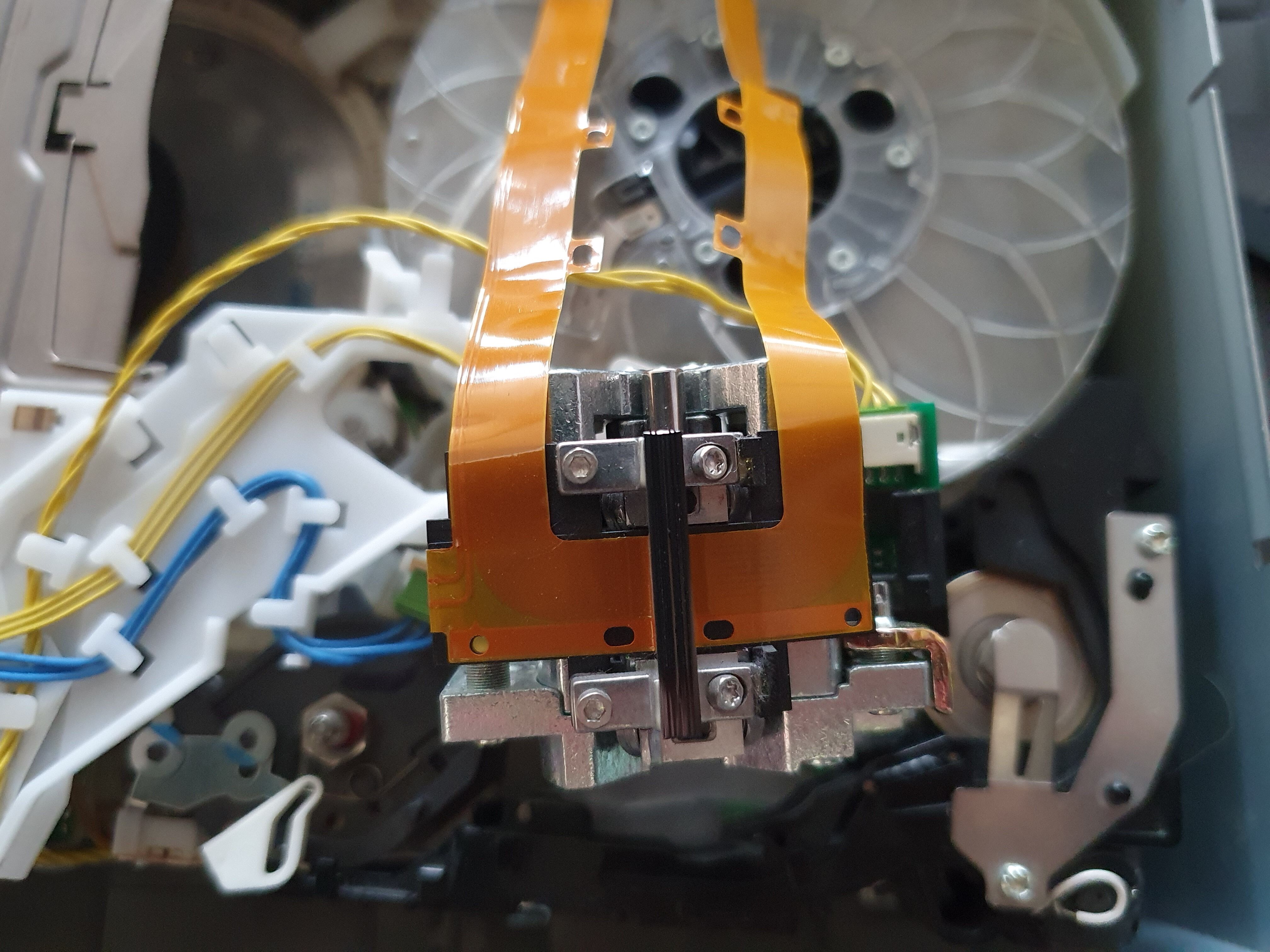
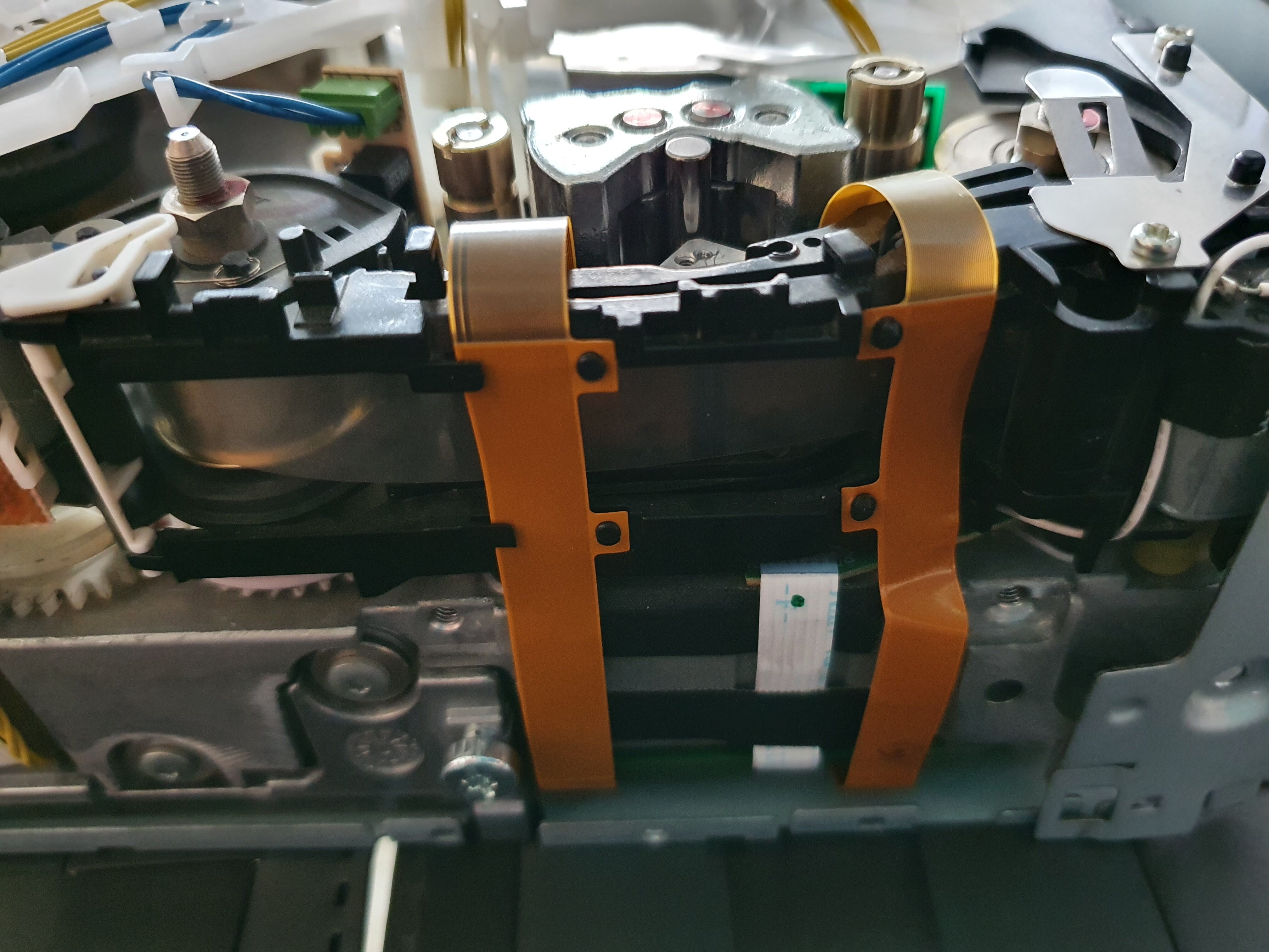
We can see the ribbon cables attached to the head assembly, and running under the drive, where they’re connected to the main PCB:
The head itself is now clearly visible:
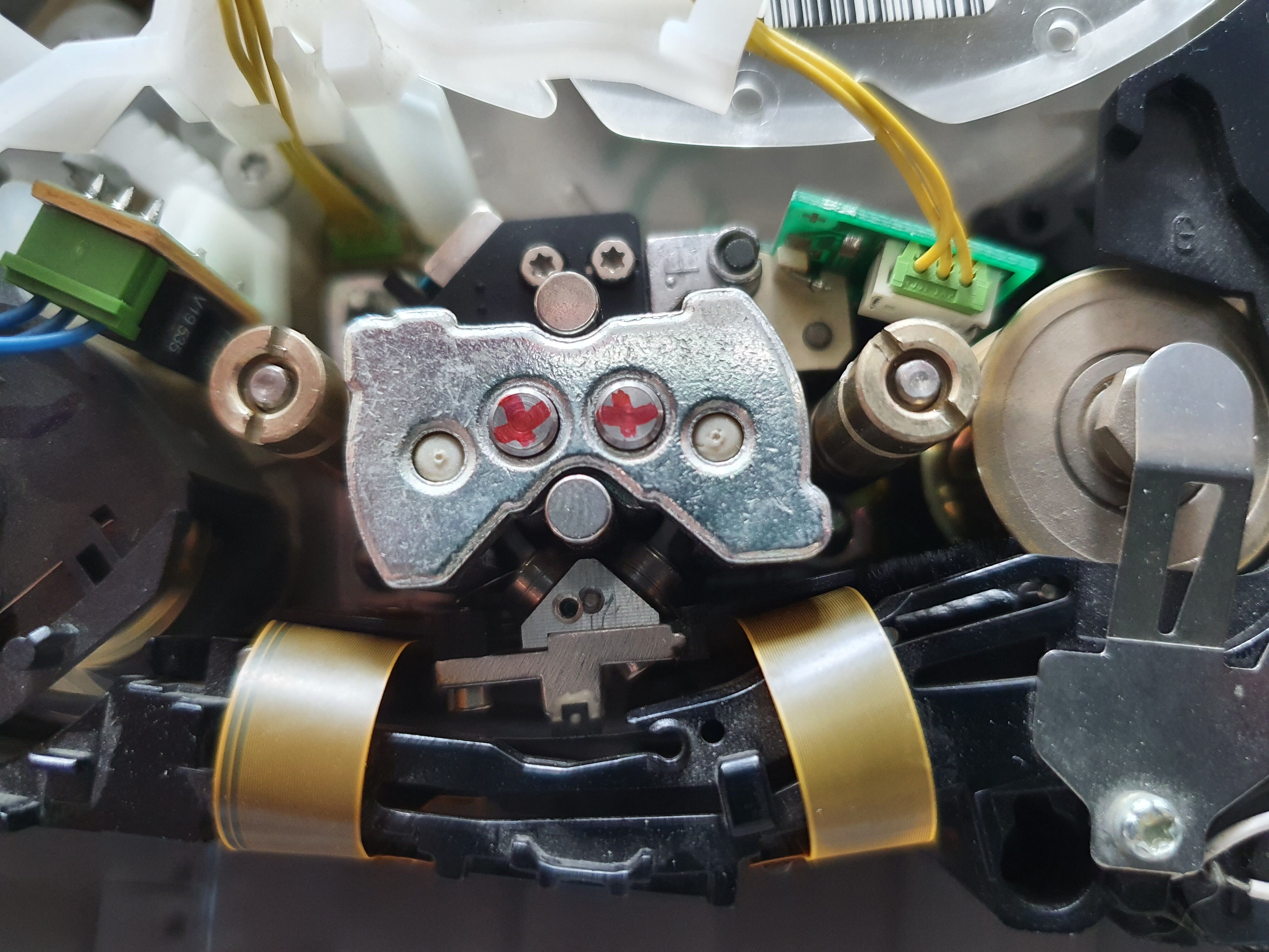
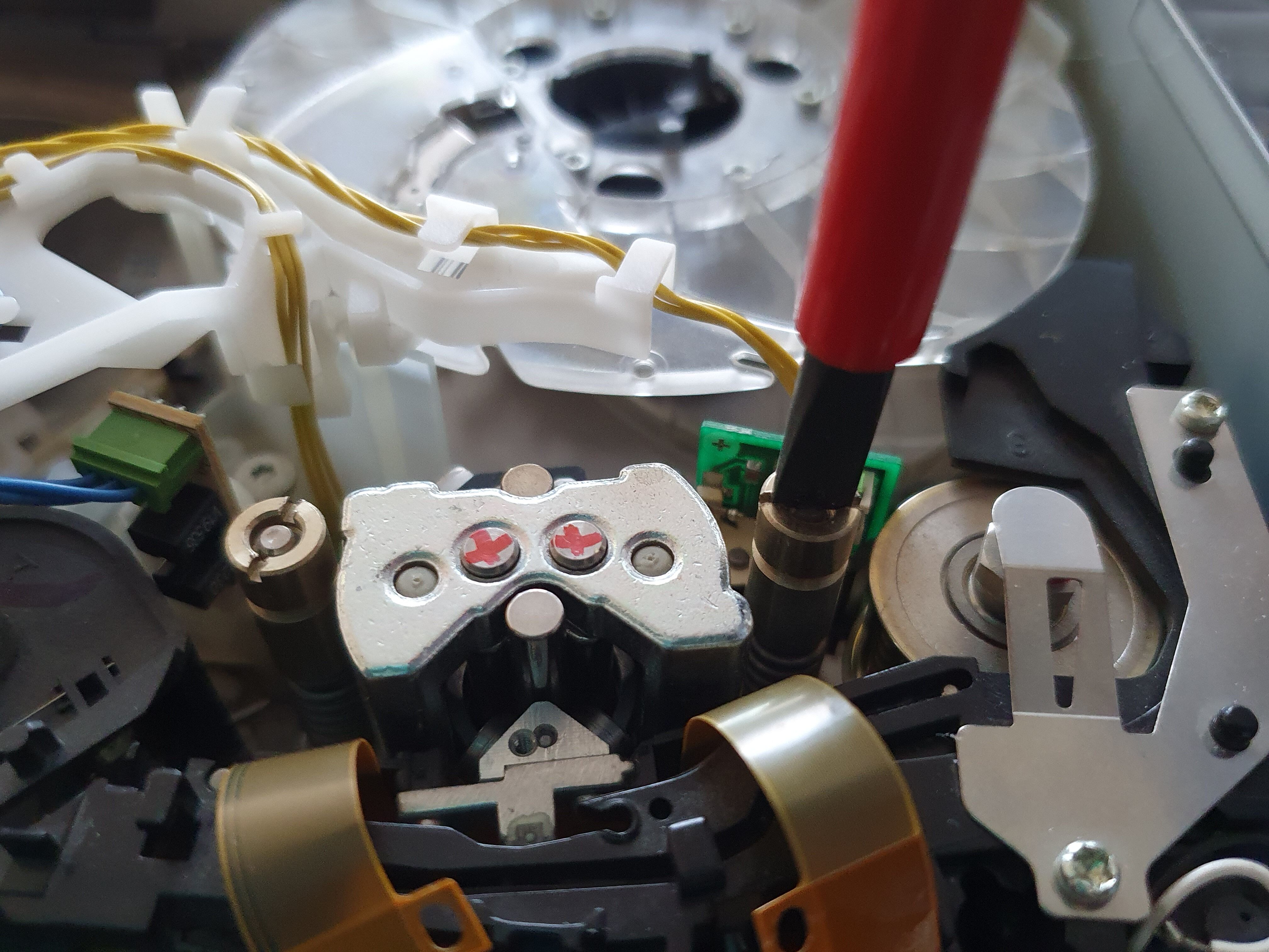
Now is the time to remove the plastic cover on top of the head assembly. You can use a screwdriver to lift it gently on the side. Just take care where your screwdriver is resting while you’re using it as a lever, you don’t want to apply pressure on a fragile part of the drive around the head assembly:
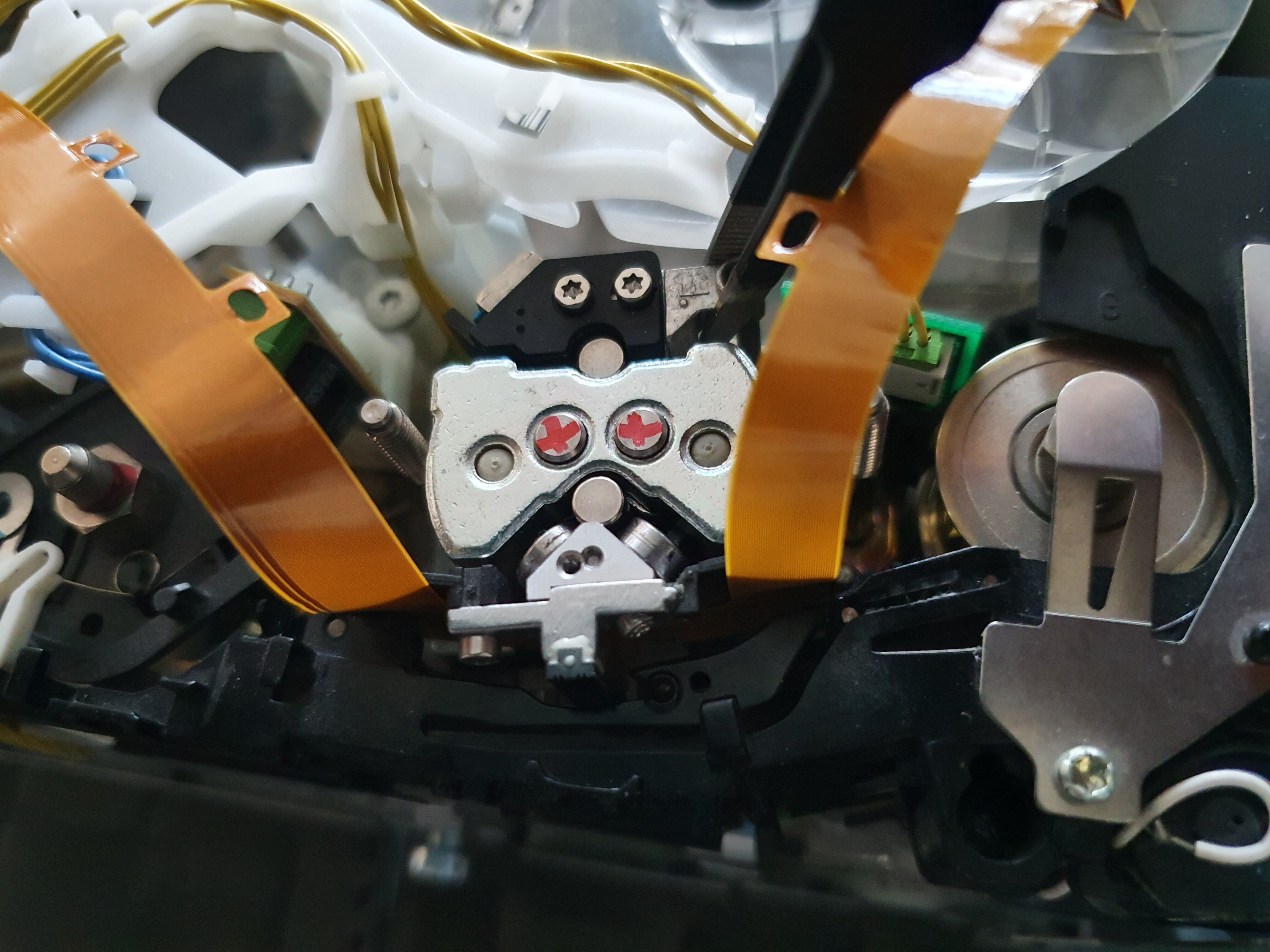
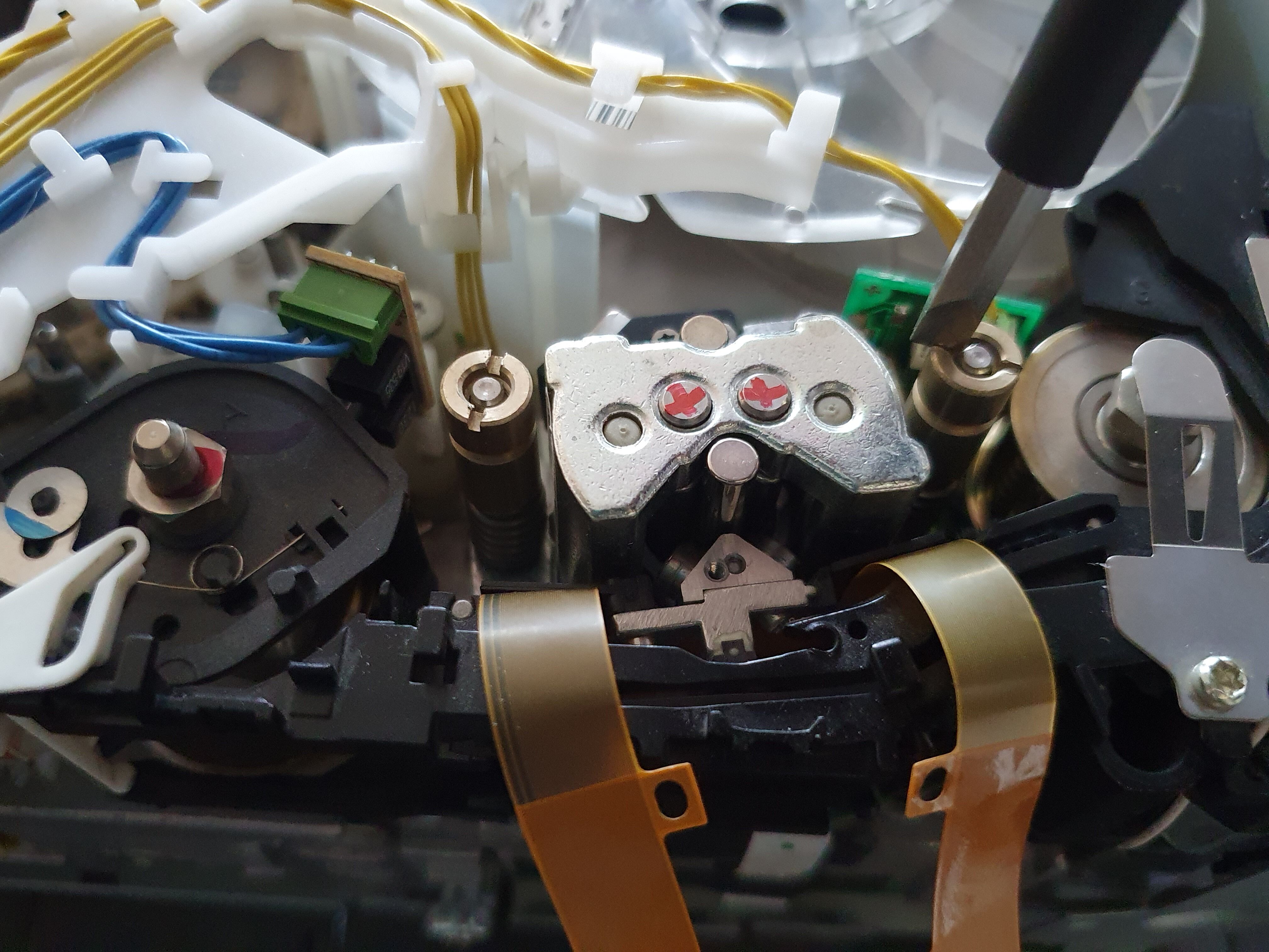
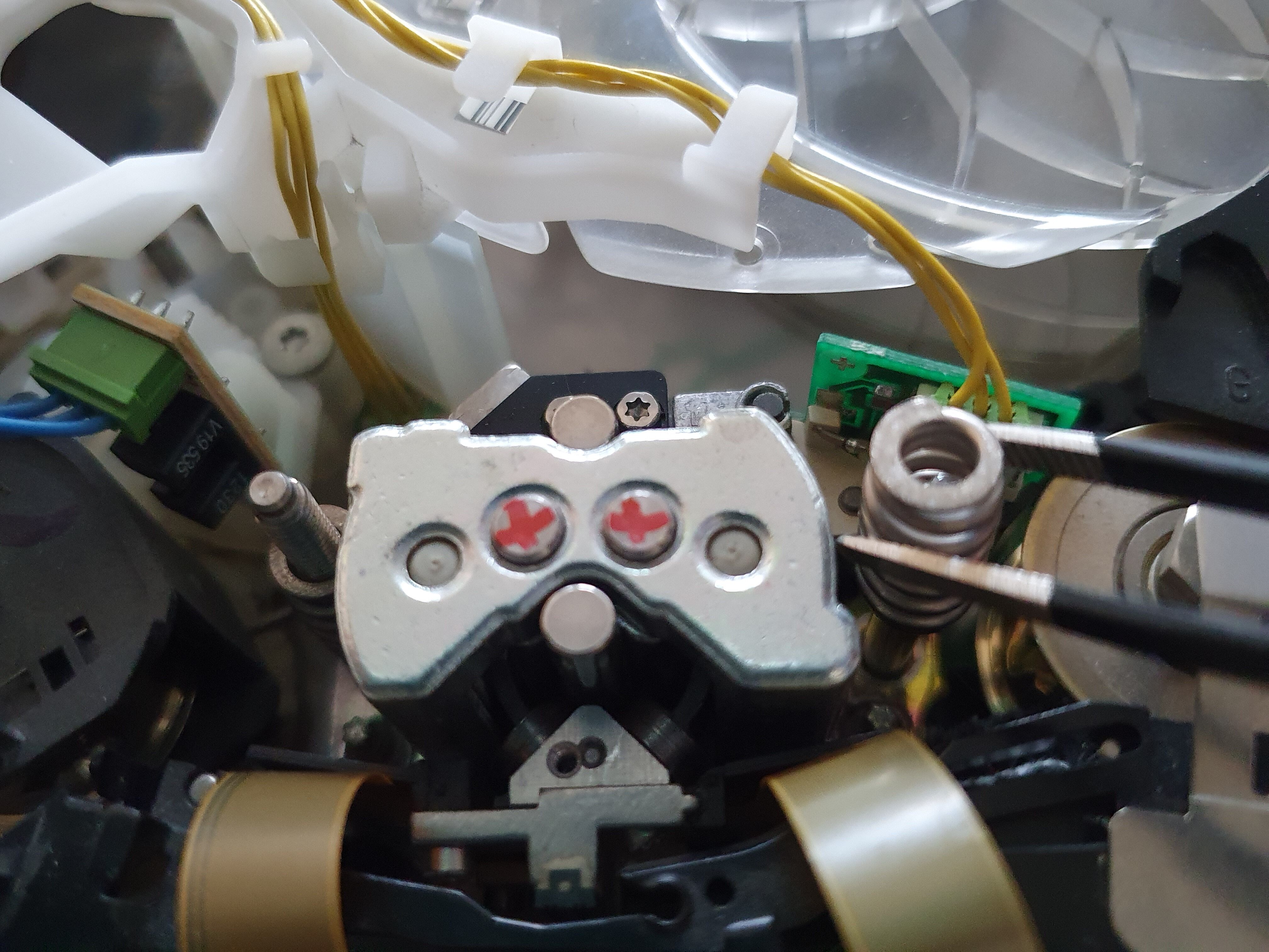
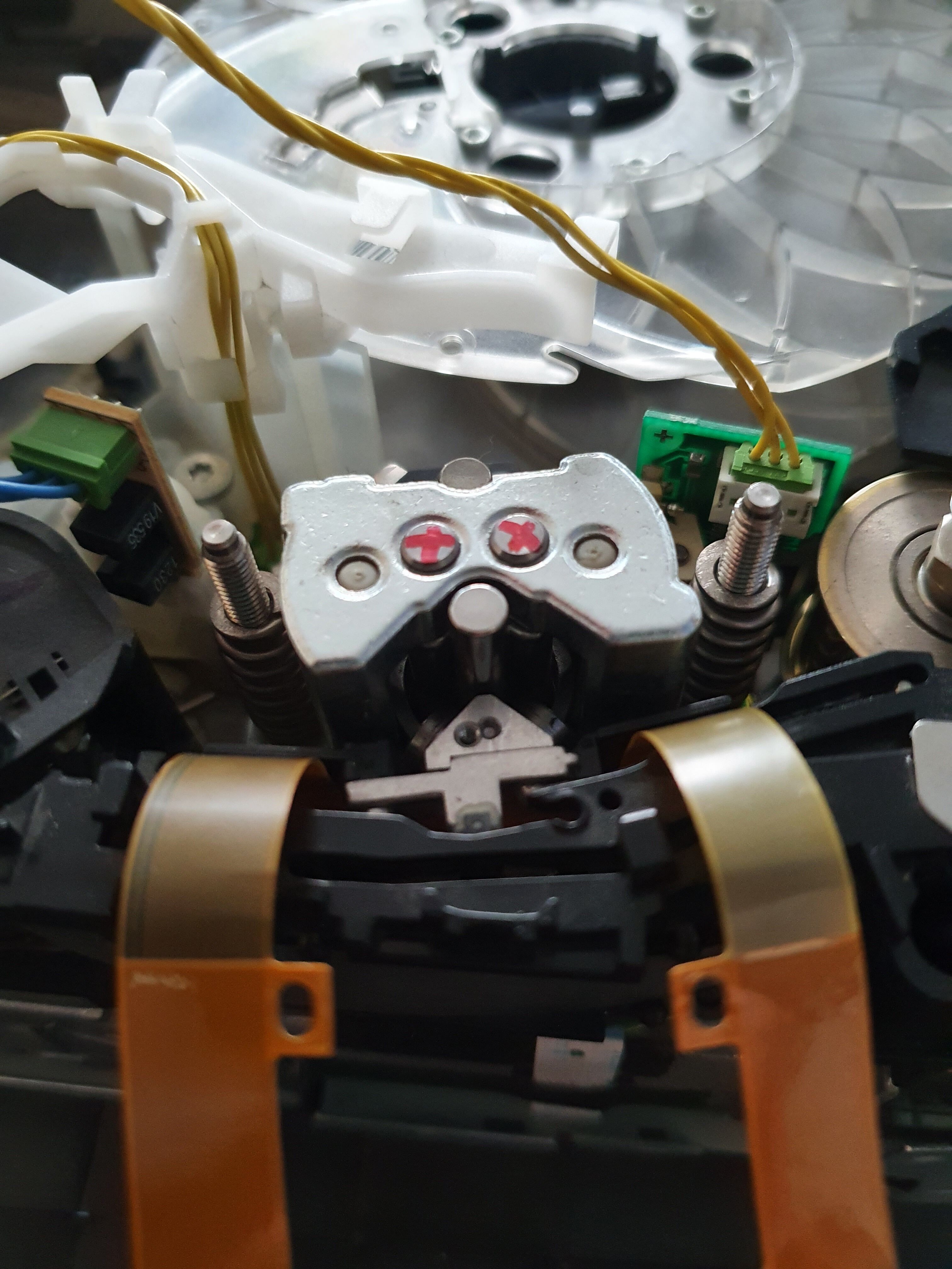
We can see the top of the head assembly. Take a pen and mark the top of the two little magnets as shown, as later we’ll remove those, and we want to be sure we put them back correctly:
At this point, the drive should look like this:
Before going further, we need to loosen the bottom cover (we don’t need to remove it), so remove the 3 following screws:
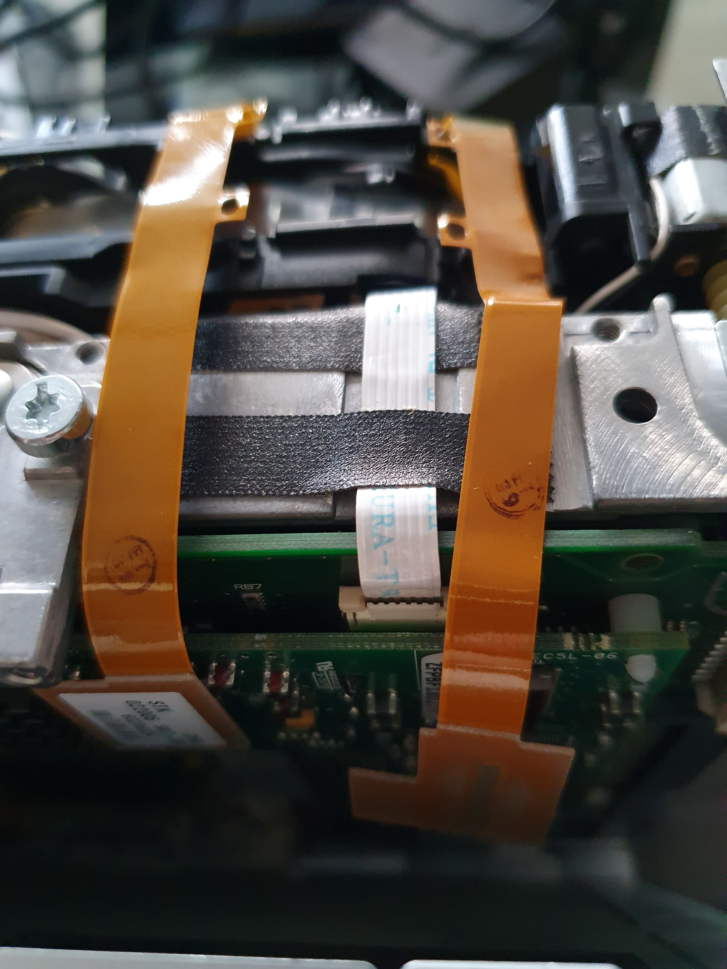
When this is done, you can put the drive on the side, and should be able to push the bottom cover back a bit, to access the proper part of the PCB. You can now gently disconnect the two ribbon cables from the PCB. Take extra caution, these cables are very fragile:

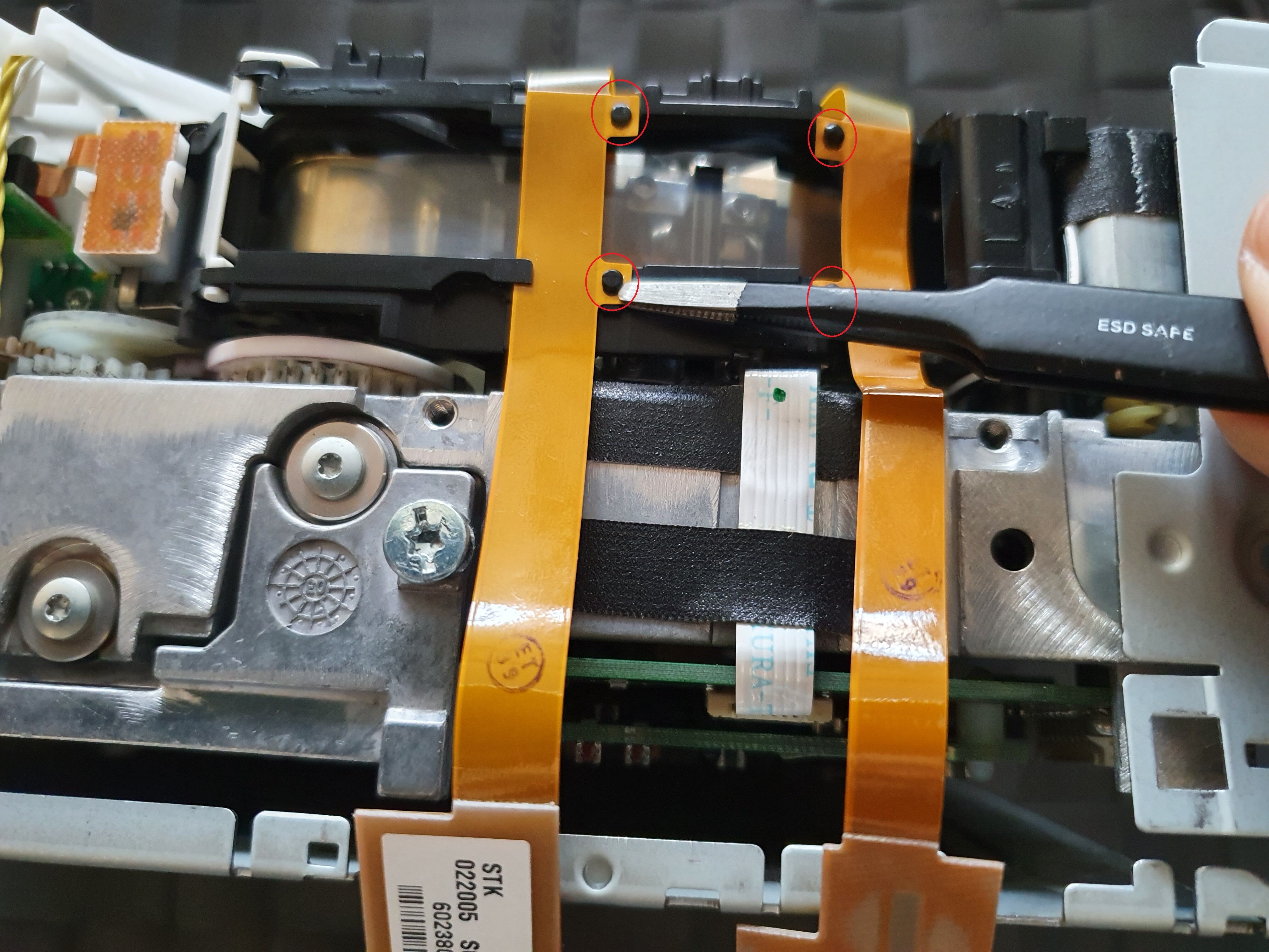
Now, let’s detach the ribbon cables, there are 4 attach points, again be gentle, this is very fragile:
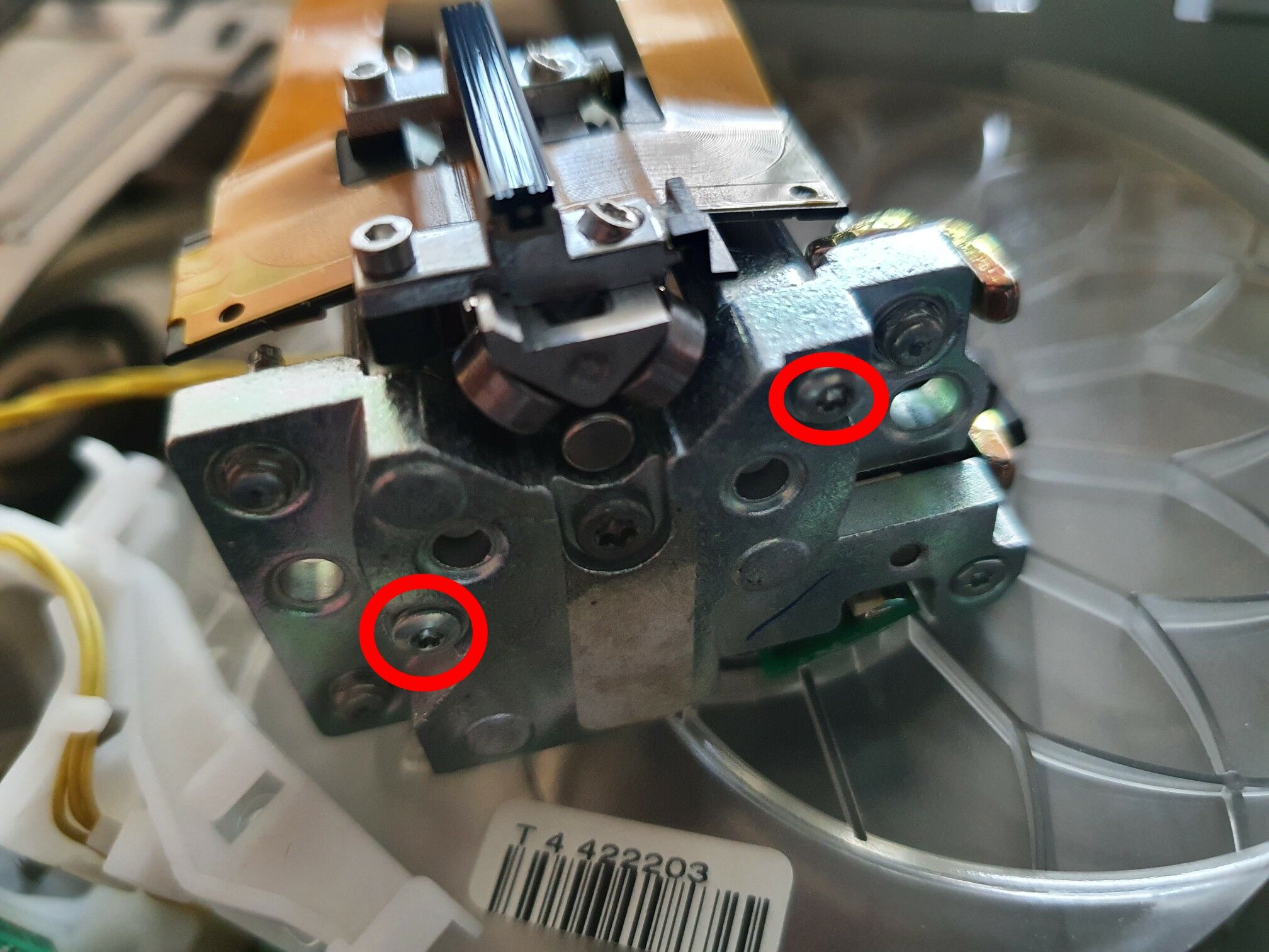
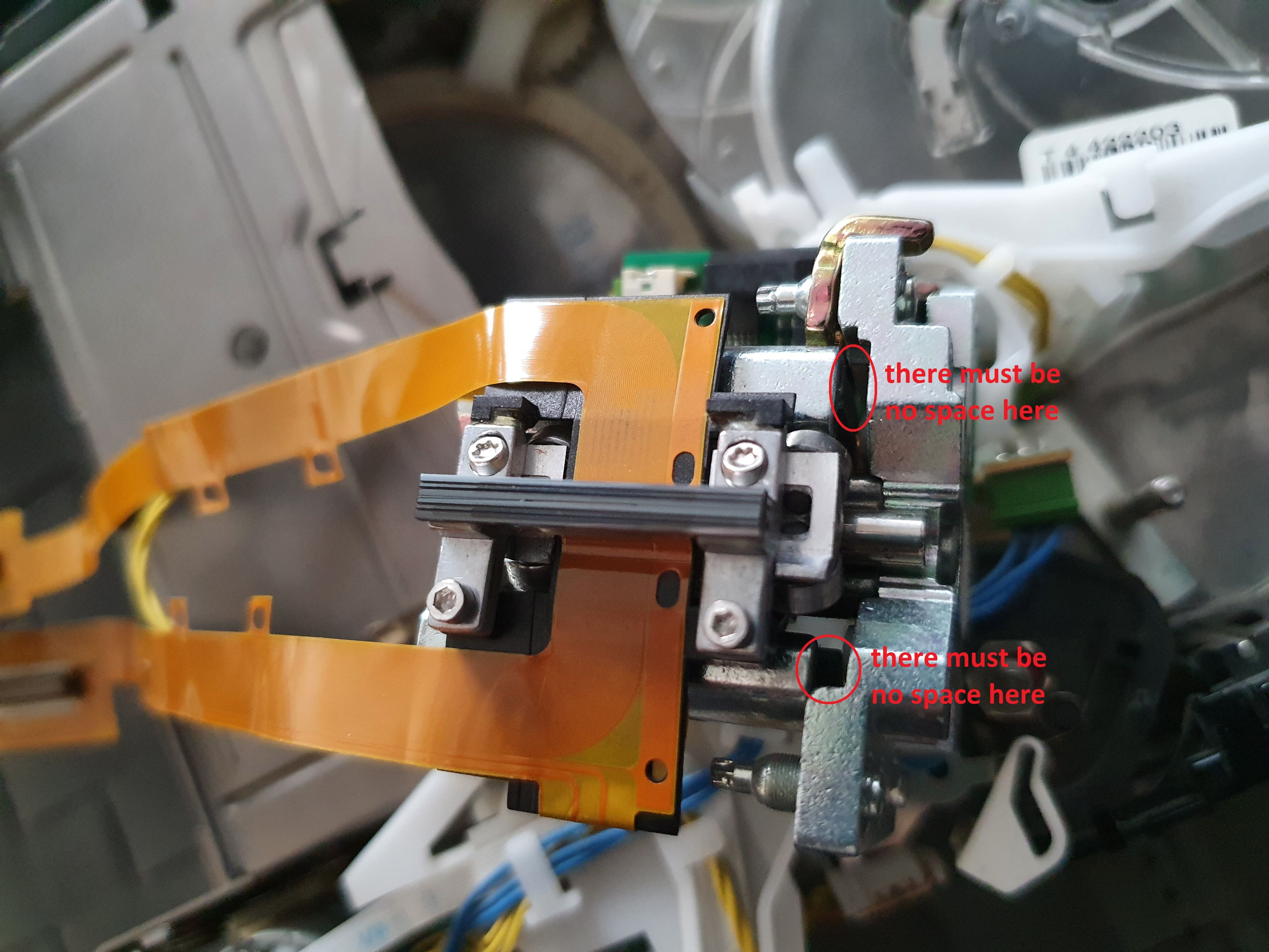
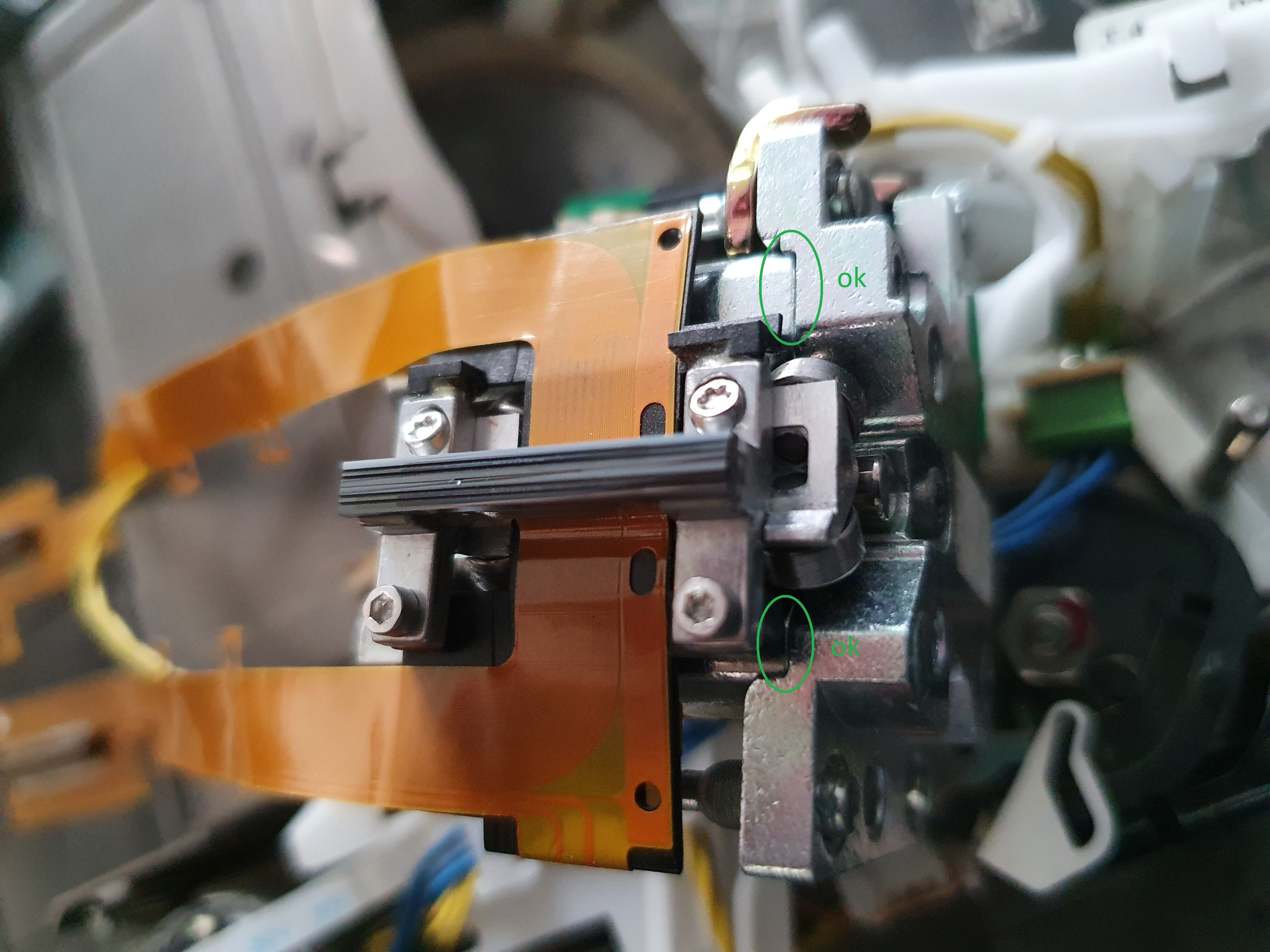
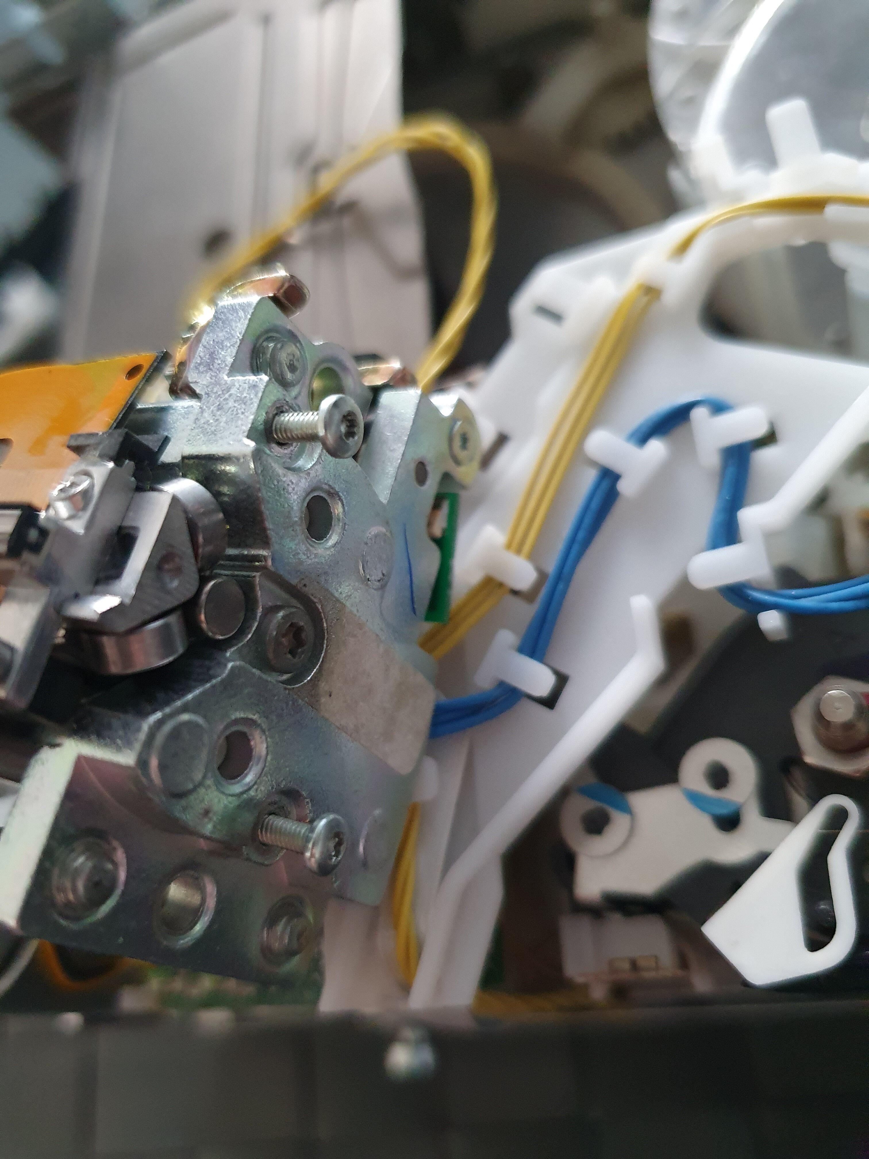
Now, we need to remove the two bolts holding down the head assembly to its base. The bolts seem to be made of some kind of brass: be gentle with the screwdriver as it might leave some marks otherwise. You won’t be able to use a screwdriver the diameter of the bolt, as the threading will prevent you to. What I did was to use a smaller screwdriver to turn unscrew the bold for the first 360 degrees:
Then, you can use a bigger one. It’s also a good idea to cound the number of turns you need to unscrew this. On my drive, it was 11 turns for each bolt:
Underneath each bolt is a spring, you need to remove those:
Before lifing the head assembly, free the head cable so that you’ll more easily be able move the head afterwards:
Now, you can grab the head assembly and lift it upwards. Don’t touch the magnetic head itself (the black part the ribbon cables are connected to):
You can then remove these two screws from underneath the head assembly base:
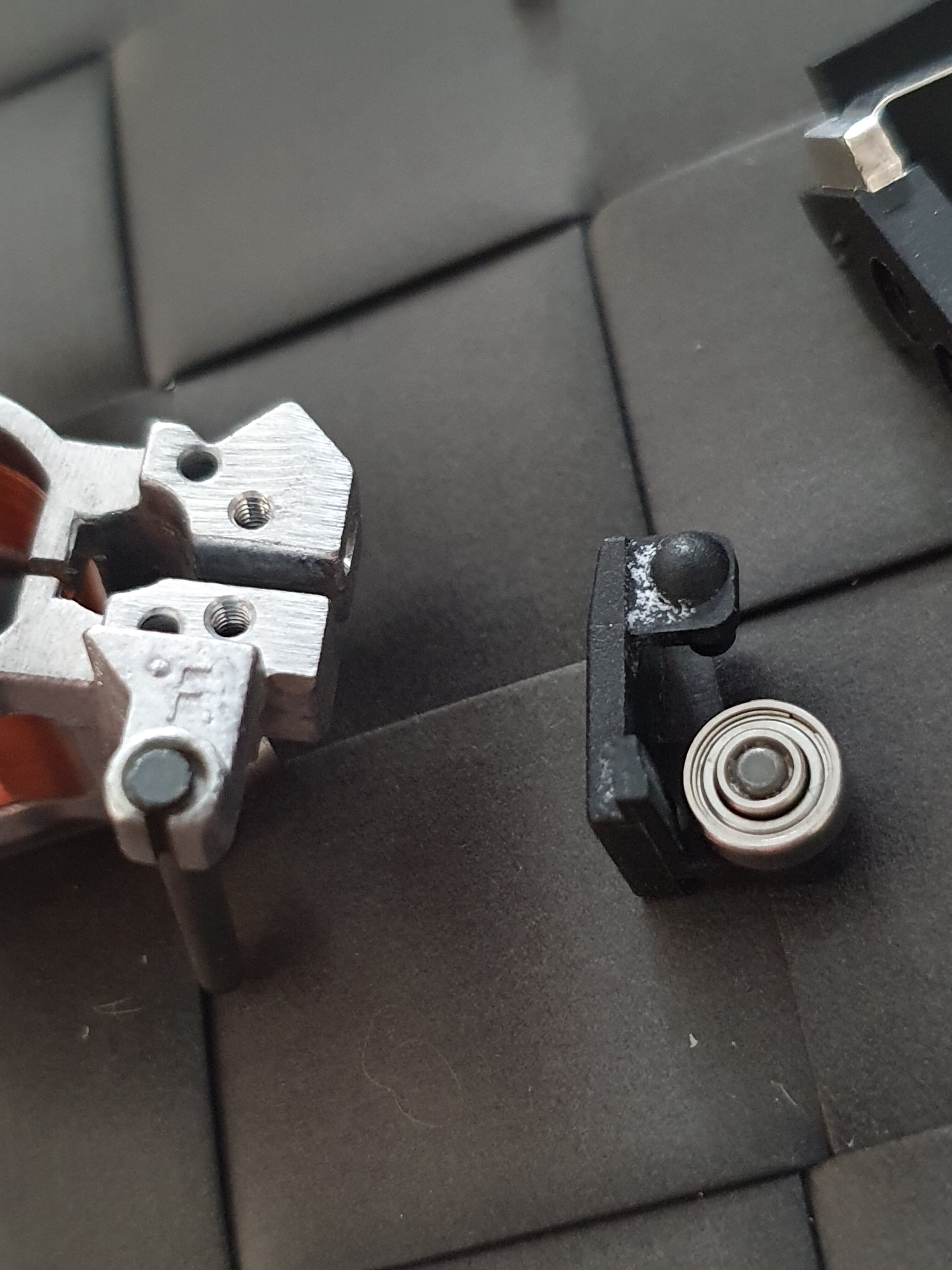
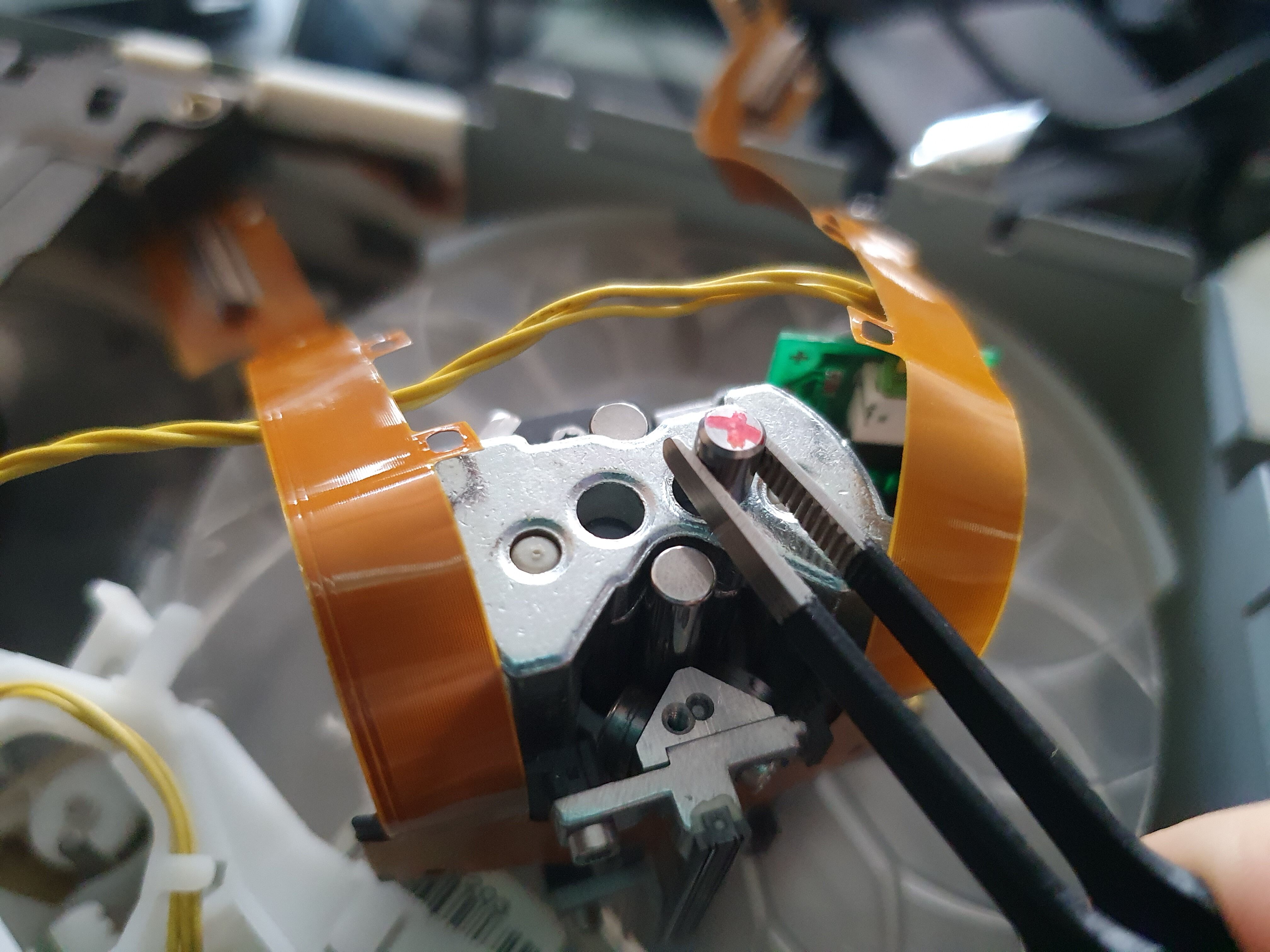
When this is done, you’ll be able to take the head assembly appart. Before doing it, check how it looks like once done:
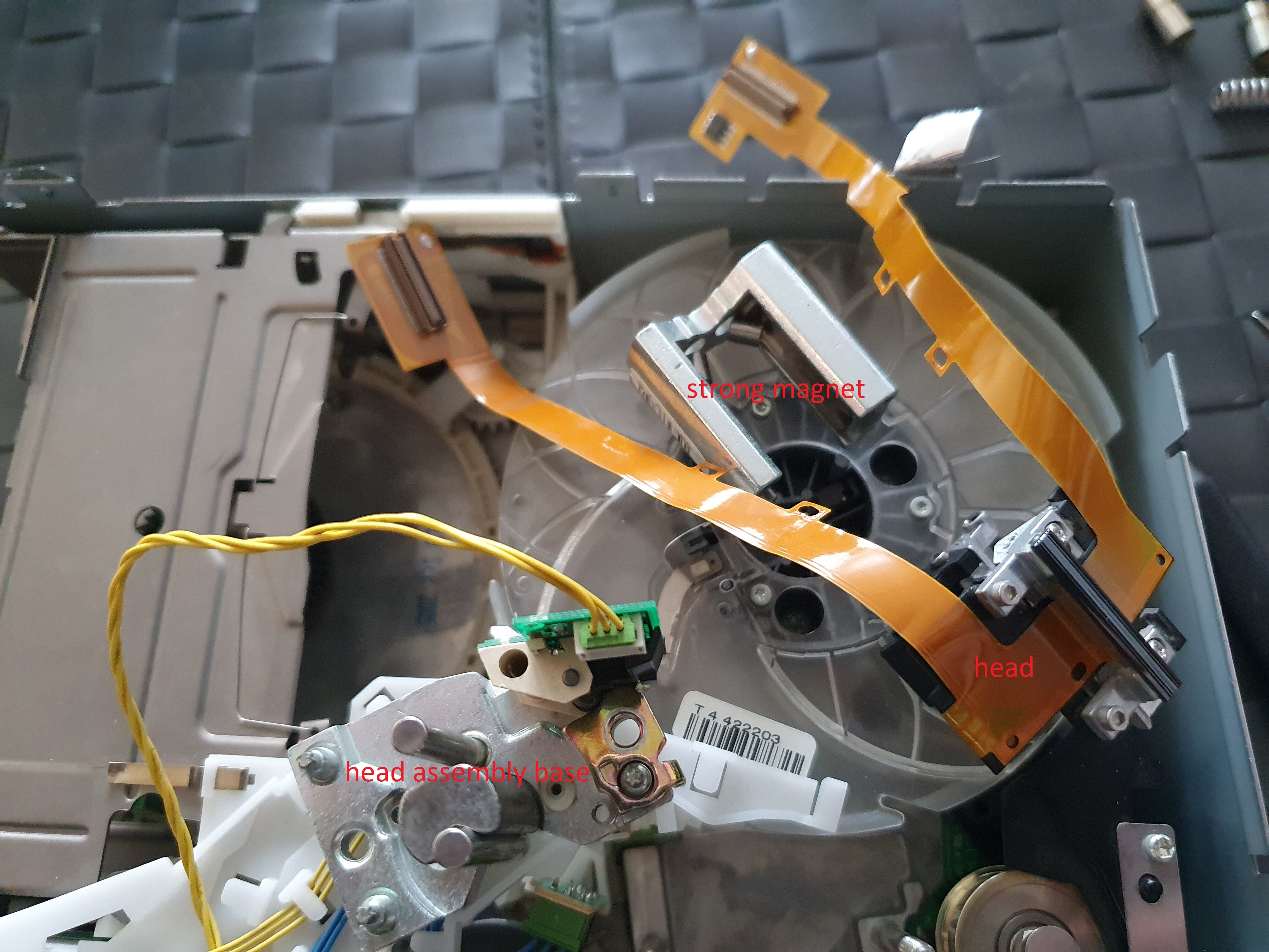
There are three parts, the assembly base, the head, and a strong magnet holding the two other together, and also part of the mechanics to move the head up and down. To disengage these three parts, hold the base assembly firmly (don’t touch the head!), grab the strong magnet firmly and lift it upwards. The two little magnets will probably move but stay stuck inside the strong magnet in some weird position (as can be seen above). Use pliers to take those away from the strong magnet and put them away to some safe place.
Now is probably a good time to have a close look on the head assembly base, and ensure there is no dirt. There wasn’t any on mine, but the only other blog I found detailing how to unmount a tape drive, had exactly this problem. The reason I decided to detail mine is that the drive is different, and my problem is slightly different too, so hopefully it’ll be useful to someone.
Here is a zoom on the head assembly, we can see 6 tiny wheels with ball bearings, from A to F:
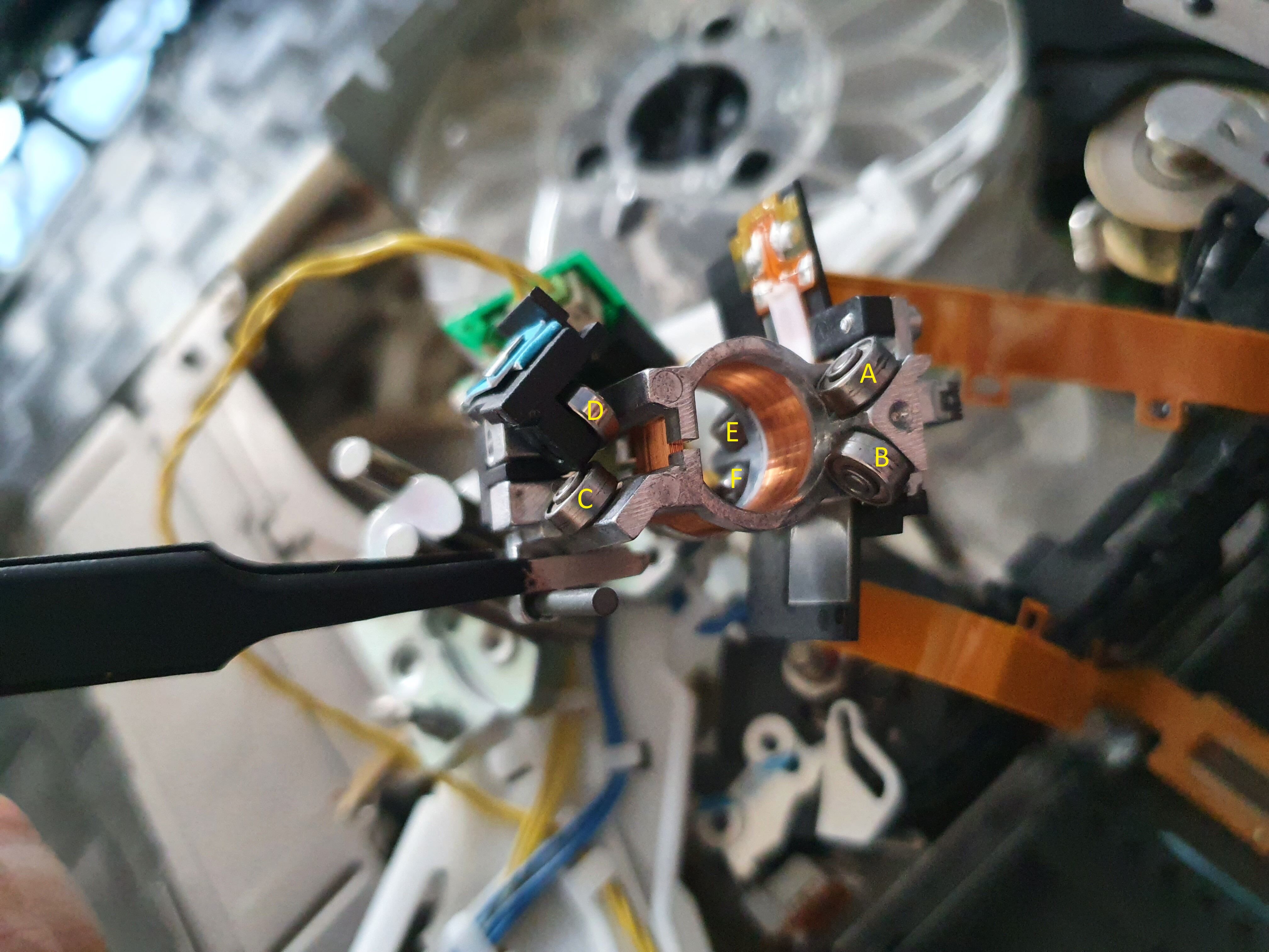
The D wheel is a bit special, it’s mounted on a black plastic part which can move a bit, and exercices a little pressure on the vertical axis it’s mounted on. This is to ensure that, even if the head assembly must move freely on the vertical axis, it shouldn’t be loose either.
The same piece but viewed from another angle, the C and D wheels are hidden behind the black plastic part on the left:

It’s a good time to test those 6 tiny wheels. They should move extremely easily when you touch them, showing no resistance at all. Just very lightly touching a wheel should be enough to make it move. Be sure to test the 6 wheels. This is was I did at first, but tested the D one a bit too fast and without enough attention, as it was harder to reach. I couldn’t find why the head assembly wasn’t moving vertically as freely as it should. It was driving me crazy, and at some point I was almost going to just trash the two drives and abort the idea of playing with tape drives completely. I took apart one last time this drive, and then made sure to really test all the wheels properly, taking my time. This is what saved the day: in my cas the D wheel was showing a little bit more resistance that the other wheels. It’s all really very subtle, but in the end as I found out, it was the cause of the complete inability of the drive to move the head on the vertical axis. Remember, it’s just using magnets, so even a tiny friction is enough to prevent it from working correctly.
Remember the clicking sounds in the video above? This is the sound the drive makes when trying to move the head with magnetic force, failing to as the resistance is too high. It tries several times, for a few seconds, before giving up and ejecting the cartridge. It’s difficult to see on the video, but by having a very close look to the head assembly, I noticed that it was moving very slightly during the clicking noises.
So, I removed the two screws on top of the black piece holding the D wheel:
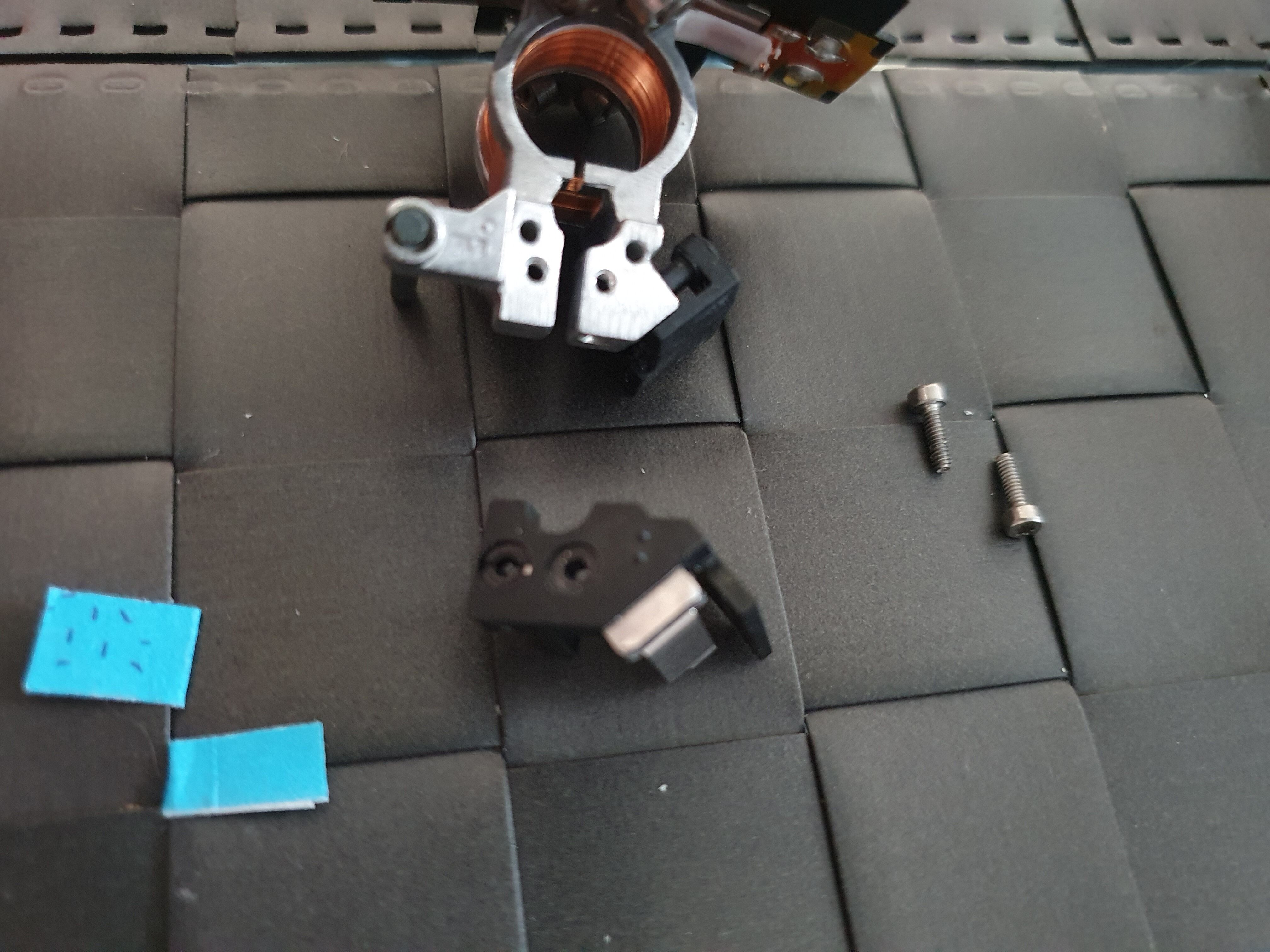
Don’t pay too much attention to the two pieces of blue paper on the photo: this is due to one of my earlier assumptions, that the system pushing the D wheel onto the axis was a bit too stiff, so I loosened it a bit (it’s the metal part which can be seen attached to the black plastic part above). It ended up not fixing the problem, and adding slack onto the axis, which is bad. This is why I added the two pieces of paper, to “undo” the loosening. Don’t do this.
Now, you can just slide the black piece out of the metal one, completely exposting the D wheel:
It was easier to test now, and clearly the wheel wasn’t spinning as freely as it should. I lubricated the ball bearing with a PTFE lubricant spray to remove the friction as much as I could.
Putting it all back together
Now is the time to test the drive again, so we need to reassemble everything. Of course, you can just follow the steps in reverse order, but as I had to reassemble everything myself too, I took some more photos.
Put the head assembly back on its base:
Then, you need to add the strong magnet on top. This is not as easy as it seems: you’ll have to work against the magnetic forces. At first you’ll probably end up with something like this:
This is not good, the big magnet needs to be attached firmly to the base, so work it out a bit more until the two parts are touching:
You can put back the two tiny magnets, ensuring that the mark you left are on top:
Then, put back the two screws under the head assembly base:
Now you can put back the head assembly as a whole inside the drive, and install the two springs:
You then need to screw back the two bolts on top of the springs. Remember the trick with the two different screwdrivers. By the way, don’t worry too much about the “head alignment” thing you might have heard about. The tapes have servo tracks that are used by the drive to align the heads properly, this is precisely why the head assembly can move on its vertical axis. As long as it can move freely without friction, and there’s no slack around the axis, it’ll align correctly thanks to the servo tracks.
Now, attach the two ribbon cables to the PCB:
Attach the ribbon cables to the 4 tiny plastic pieces:
Attach back the yellow cable, and put its plastic top on the head assembly:
Attach the black cover, protecting the ribbon cables, and put back the two screws:
We no longer need the bottom cover to be loose, screw in the 3 front screws:
Now put back in place the right metal cover, slide it properly inside the bottom cover and the right cover, then put back the two screws holding it in place:
Put back thee top cover, remember there are no screws here, just stickers:

And finish with the front bezel and its four clips:
We’re done! I ran a drive assessment test in L&TT, and lo and behold, it showed no errors.
Time to finally have some fun experimenting stuff with this drive!